Project Download:
Transclude of Final-Project-First-Sketch-v20.f3dThis documents how I modeled a prototype of my final project in fusion. First I had to model the Flipdot Display which I will be using, after that I created the Frame.
More detailed Descriptions of the modeling process will be added in the future.
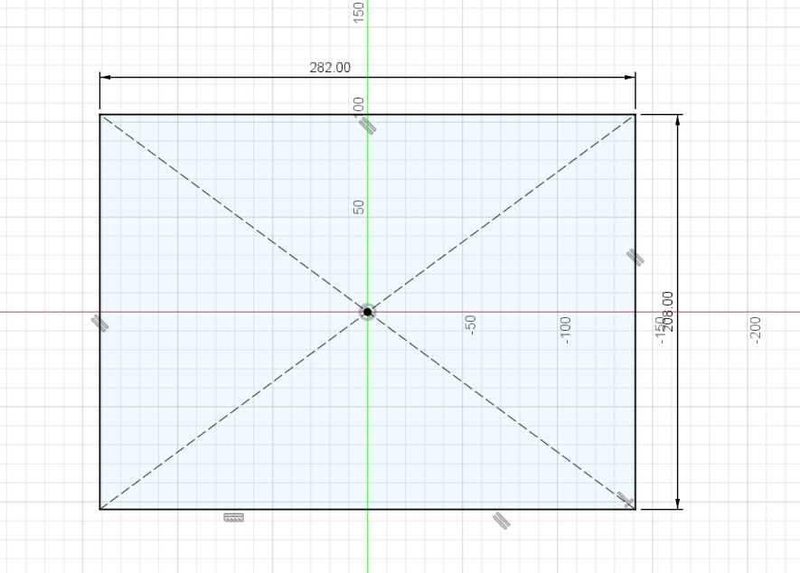 created a sketch, center rectangle with dimensions according to the actual physical flipdot display.
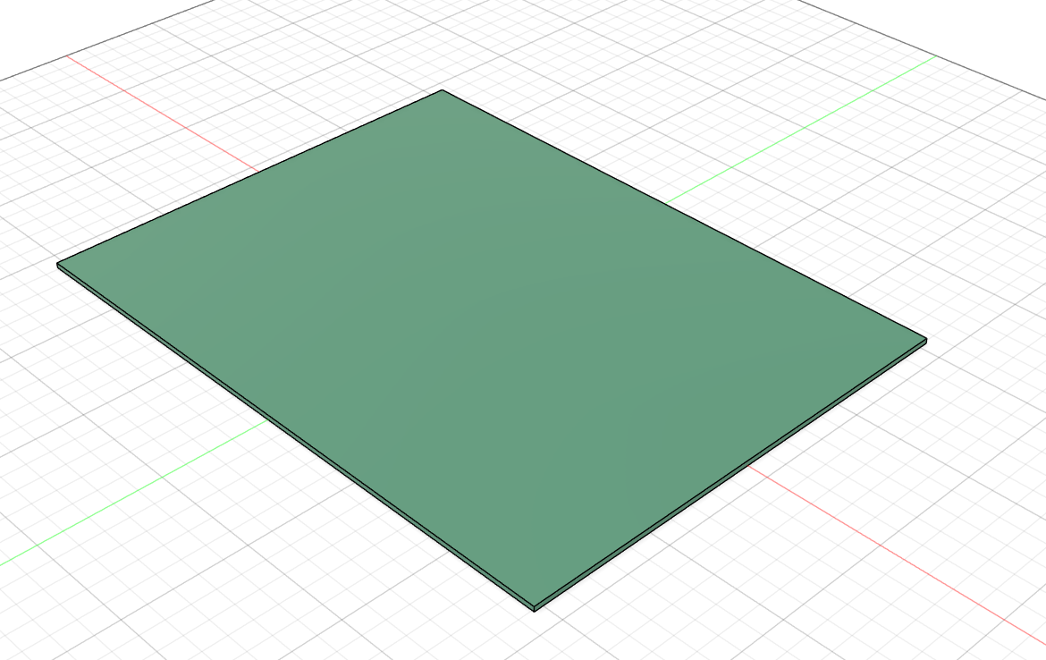 extrude the sketch, added appearance
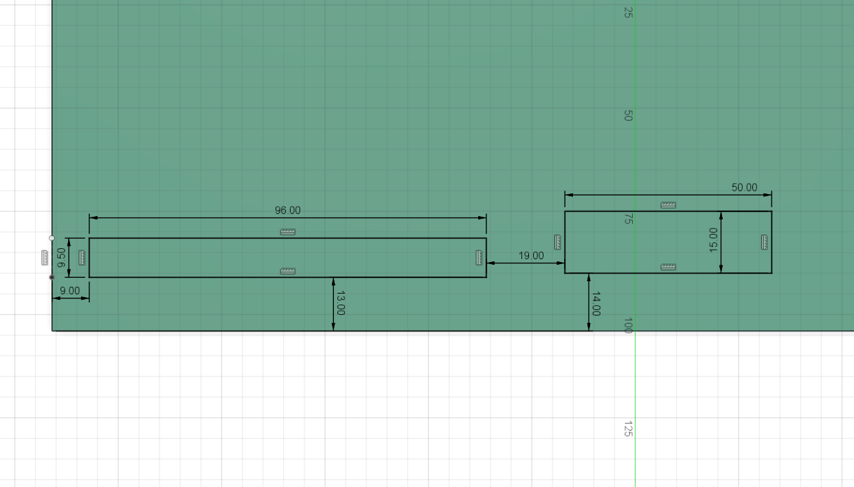 created a new sketch. rectangles according to the connectors and circuit on the physical display
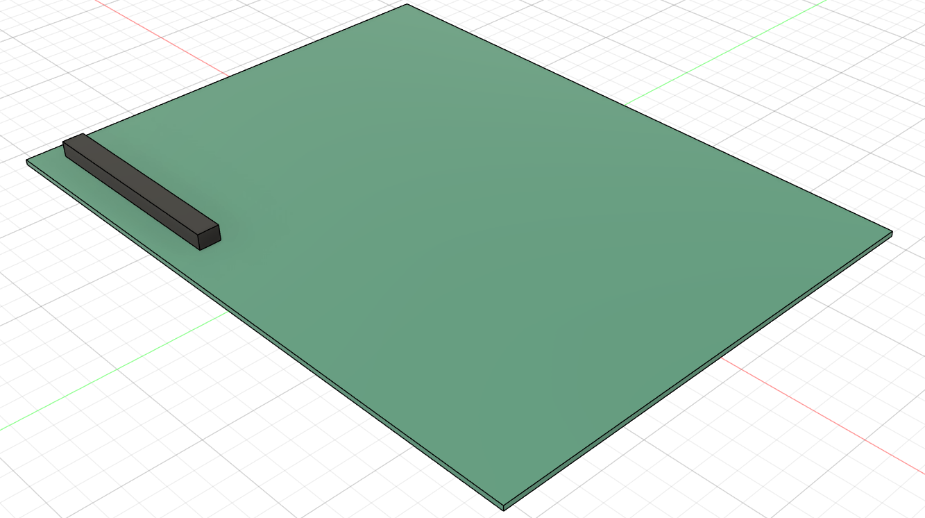 extruded the sketch for the left connector
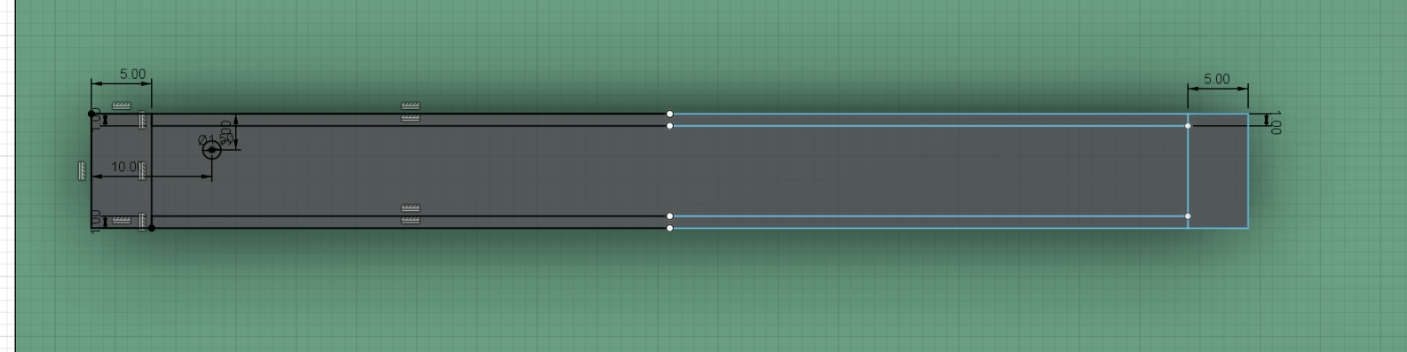 created a new sketch, made rectangles according to the physical connector
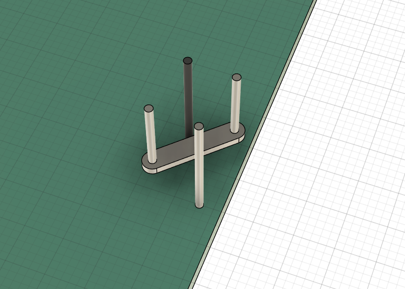
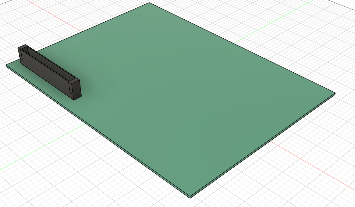 extruded sketch to create shell of the connector
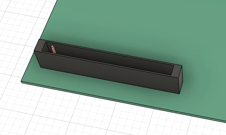
modeled one pin, by extruding a circle and applying chamfer
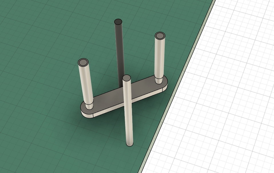
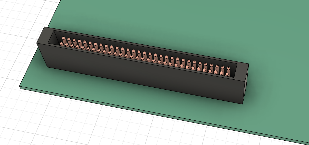 used rectangular pattern tool to copy the pin and create the complete connector
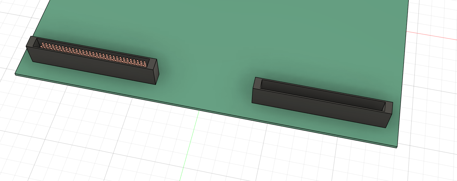 mirrored the connector shell
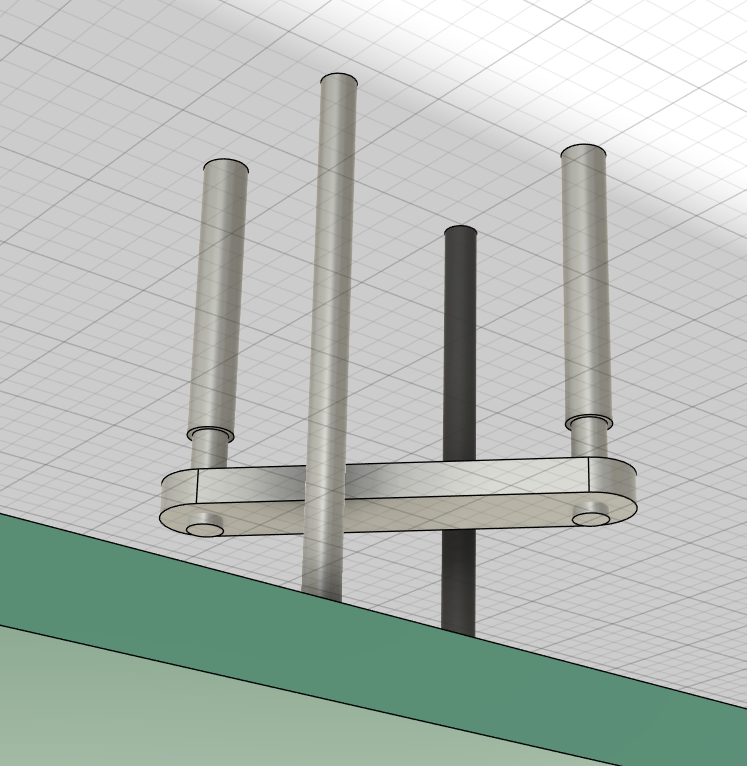
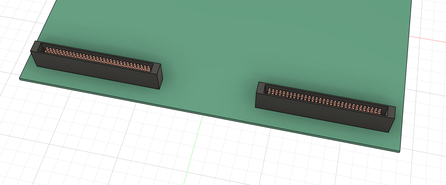 mirrored the pins
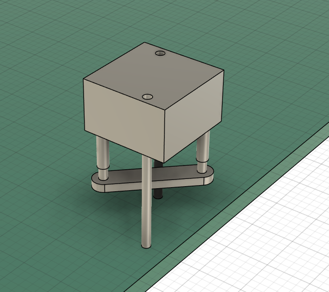
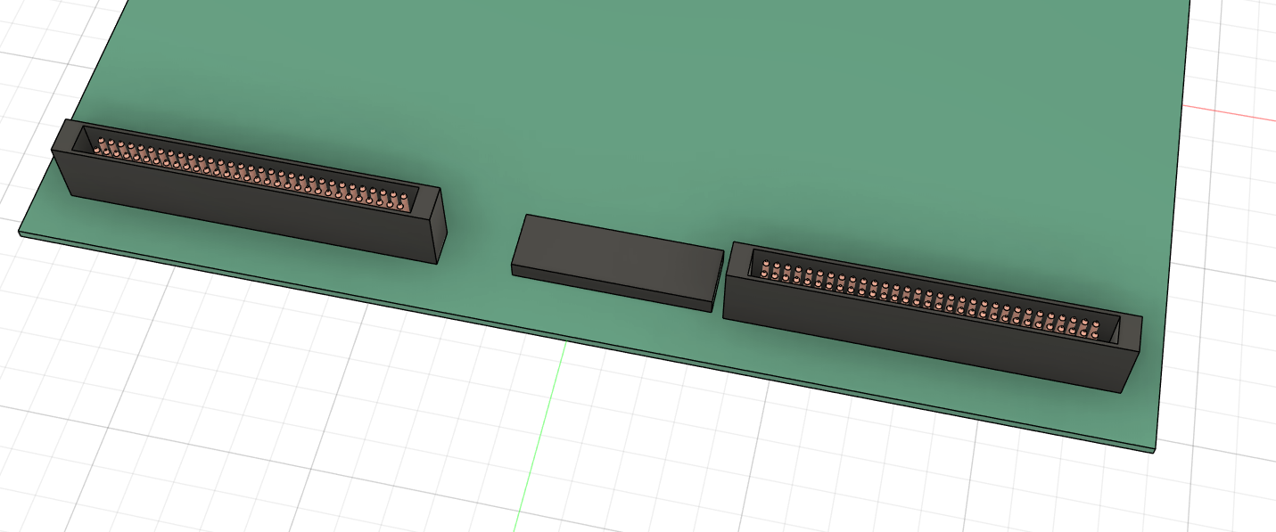 extruded the other rectangle to resemble the chip on the display
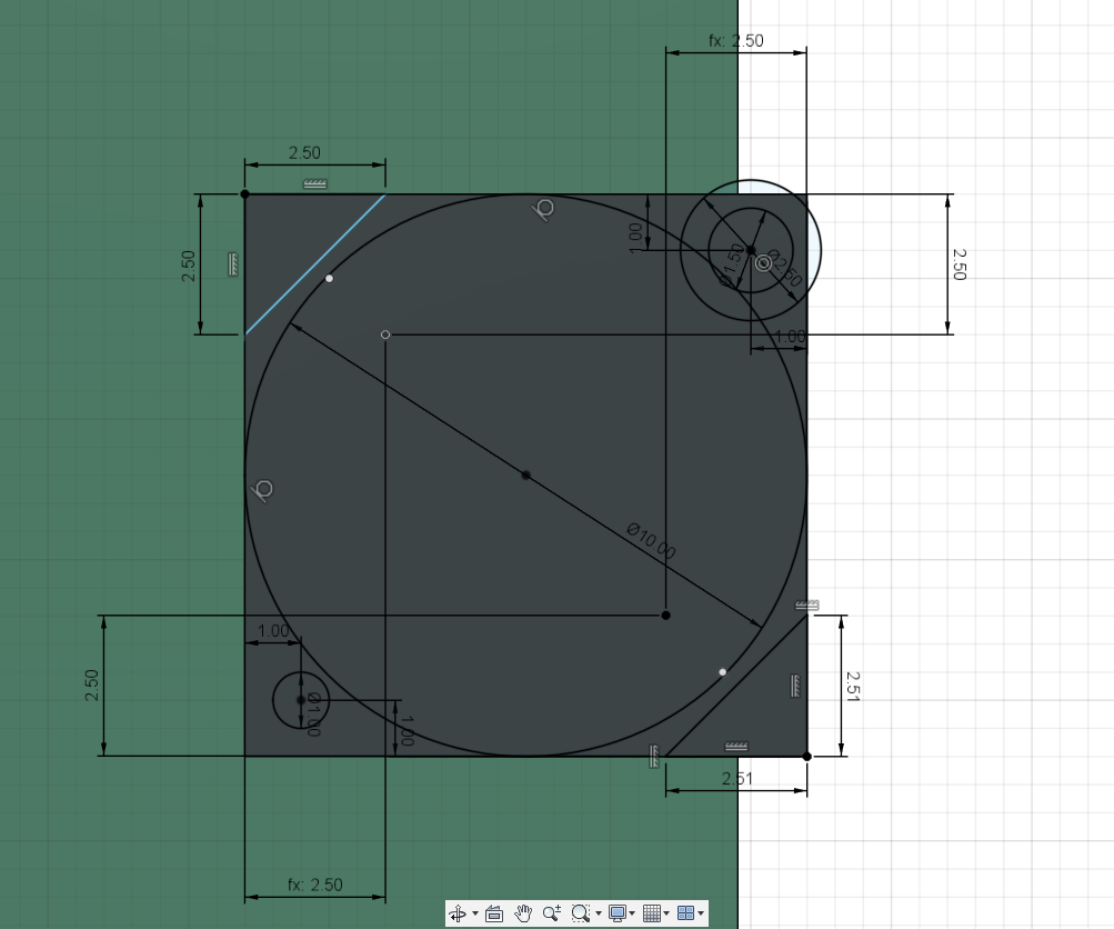
 to model the single flip dots, started with a sketch, created a rectangle and circles for the pins, created another rectangle, chamfered the corners and used move to turn 45 degrees
extruded the pins connecting the single flip dot to the base plate
 extruded the connecting plate, using an offset
 created another sketch, drew circles for more pins and something to resemble the wire wrapped around them
 extruded the inner circle to create the pins
 extruded the outer circle with an offset to mimic the copper wrapped around the pins
extruded the inner circle into the negative to resemble the connection in the physical
extruded the rectangle with an offset to create the base holding the flip dot

filled in the holes using extrude tool
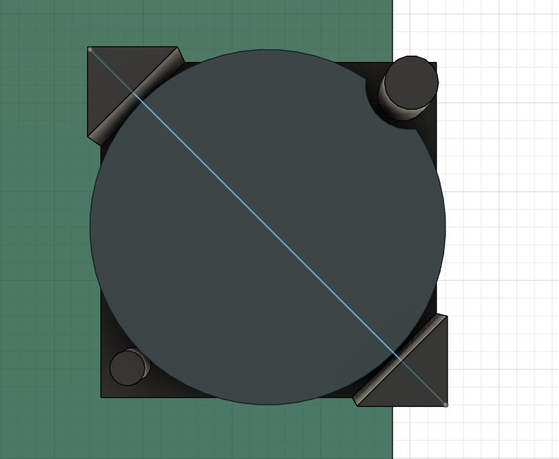
 created a sketch for the flipdot,
extruded the outer triangles connecting the flip dot to the base
extruded the circles to mimic the physical dot, these create the electromagnet to flip the dot
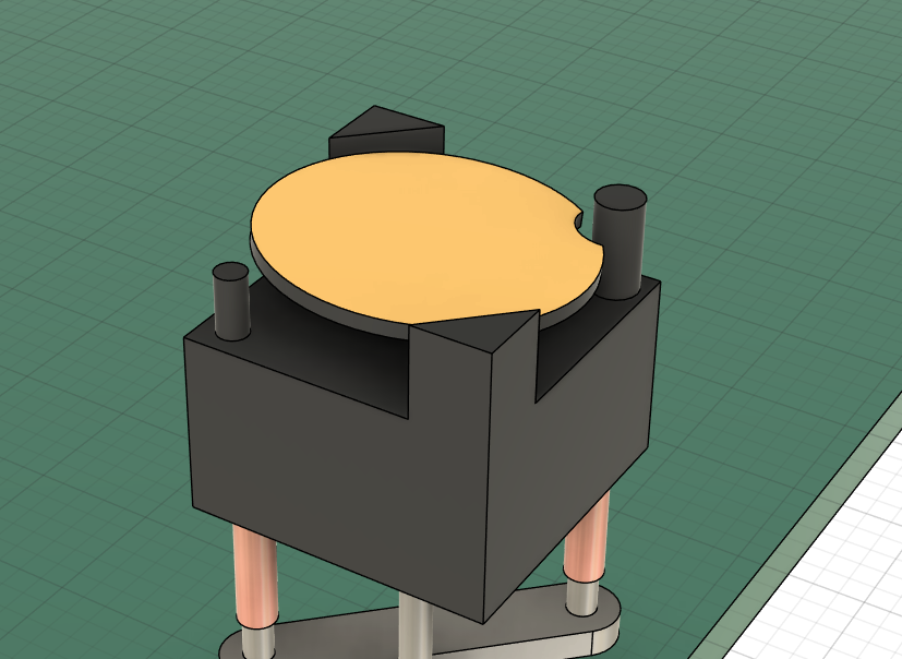
extruded the circle, save for the cutout, this is the flipping dot. Started adding appearances
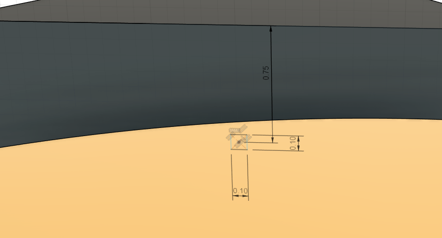
 created a new sketch, made a line, this is the axis the dot is on
 tilted the dot along the axis by 5 degrees to mimic the physical dot
 created sketch, rectangle is the axis connecting the dot and base
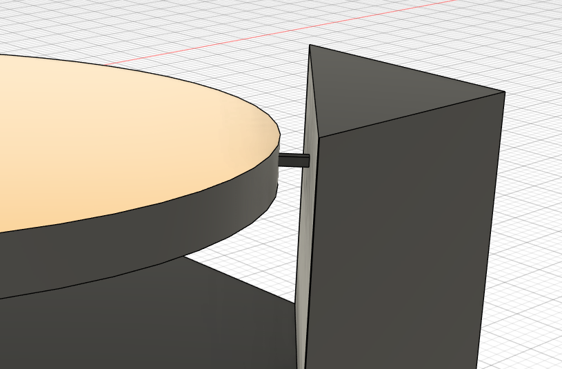 created the axis by using the sweep tool and choosing the rectangle and axis created above
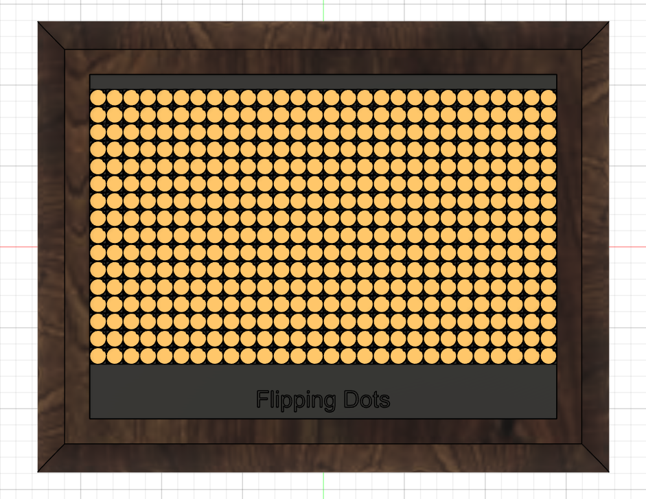
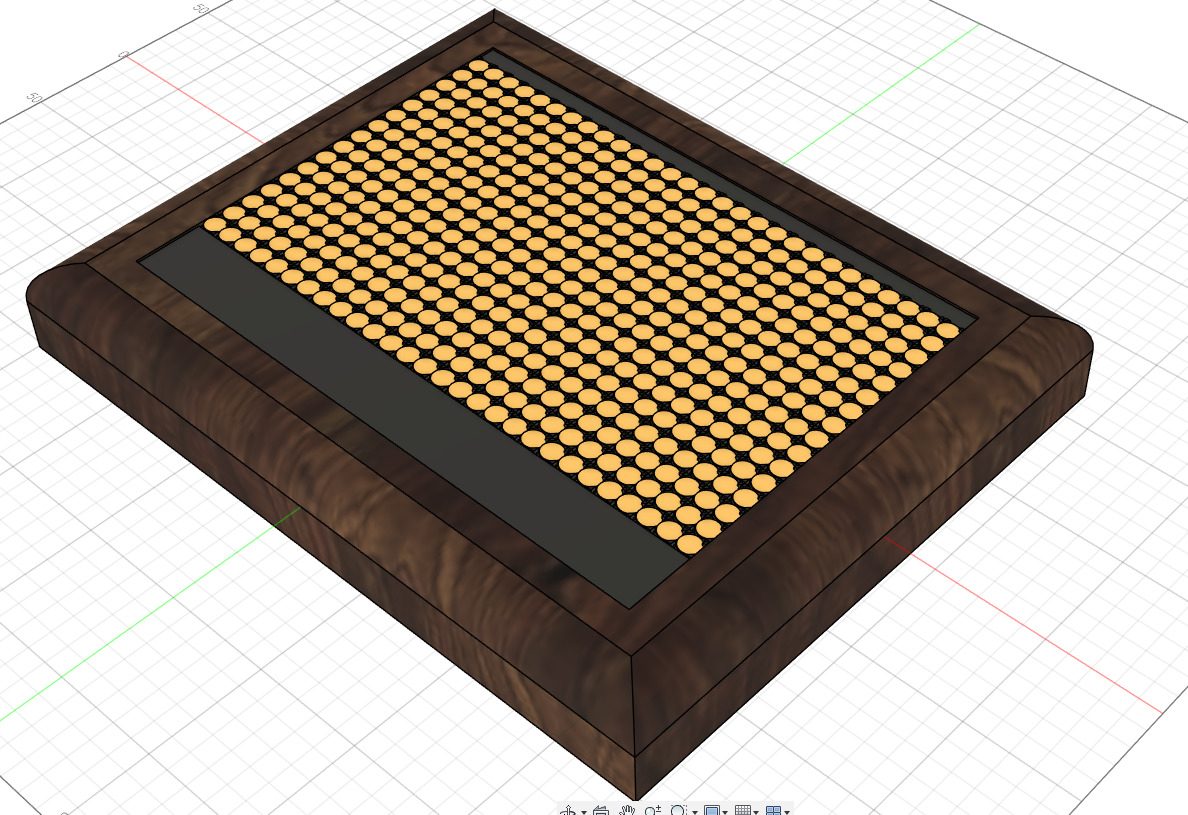
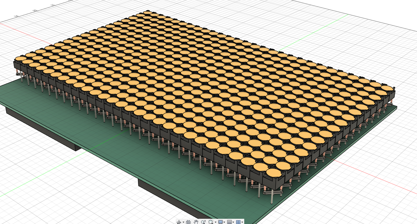 multiple combine steps have not been mentioned, used the rectangular pattern tool to copy the one dot along two axis creating the full display
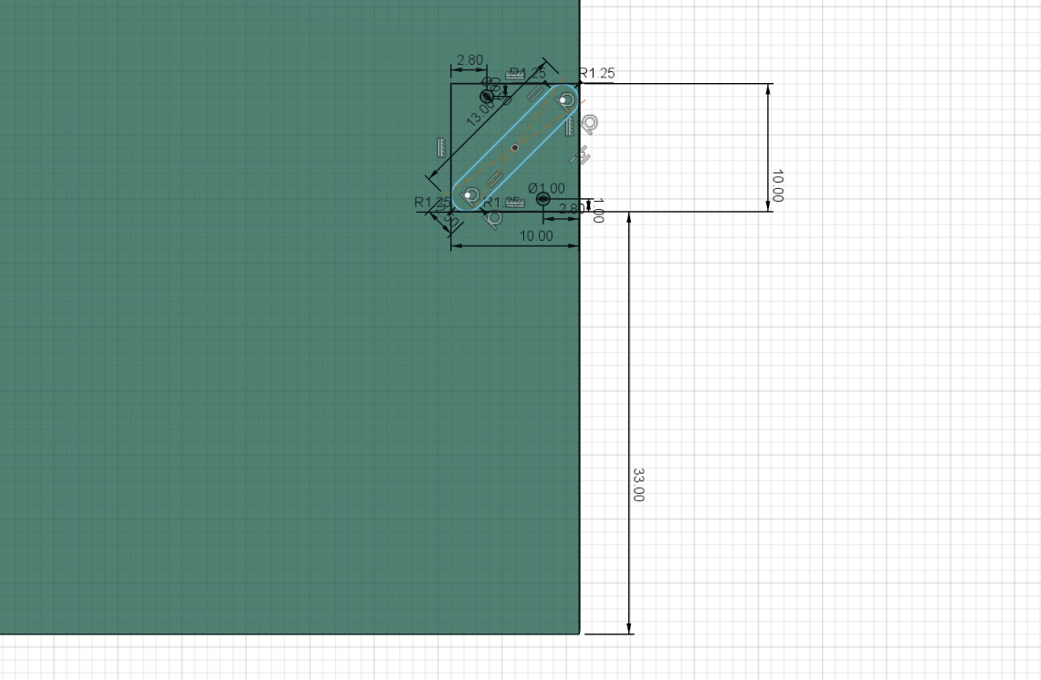
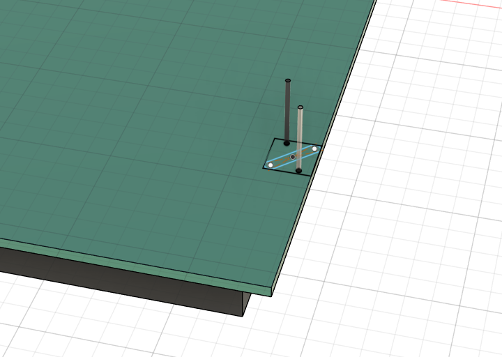
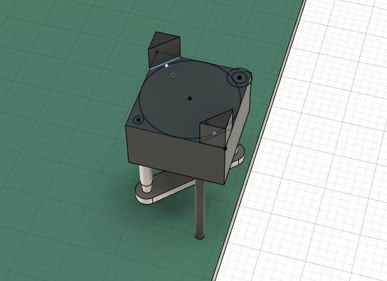
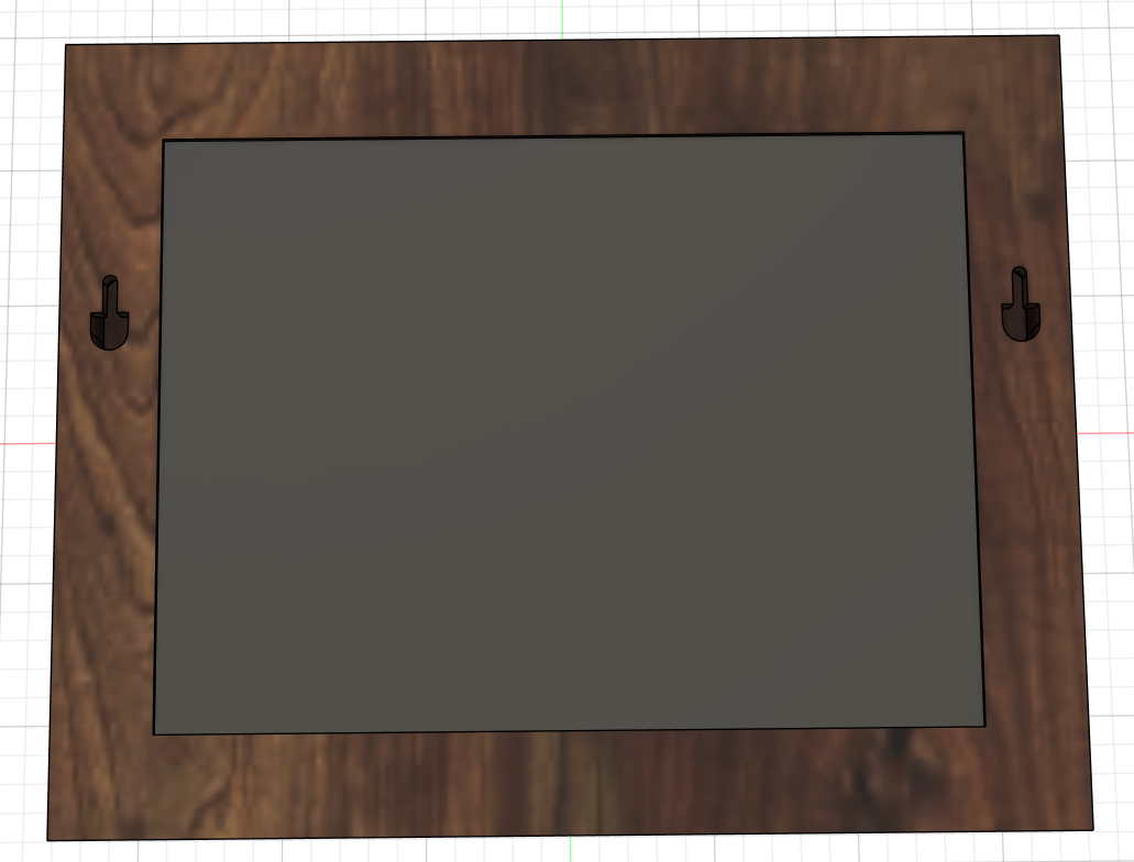
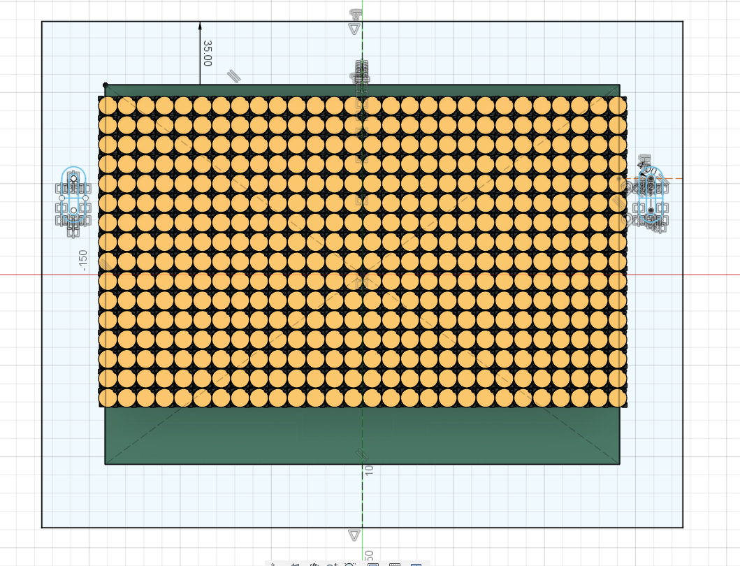 created a sketch for the frame, using a center rectangle, created two slots to hang the frame. These are made with the center to center slot tool and a line to be able to extrude the slots
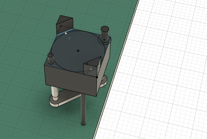
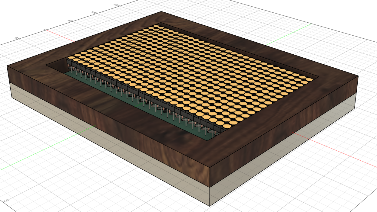 extruded the frame in both directions
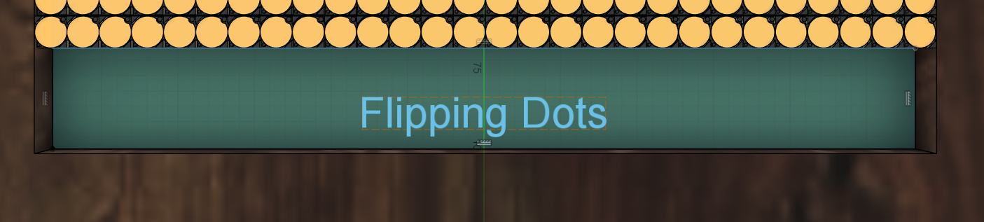 created another sketch, made two rectangles and a text to engrave
 extruded the two rectangles as a cover using an offset, extruded the rectangle on the backside at an offset
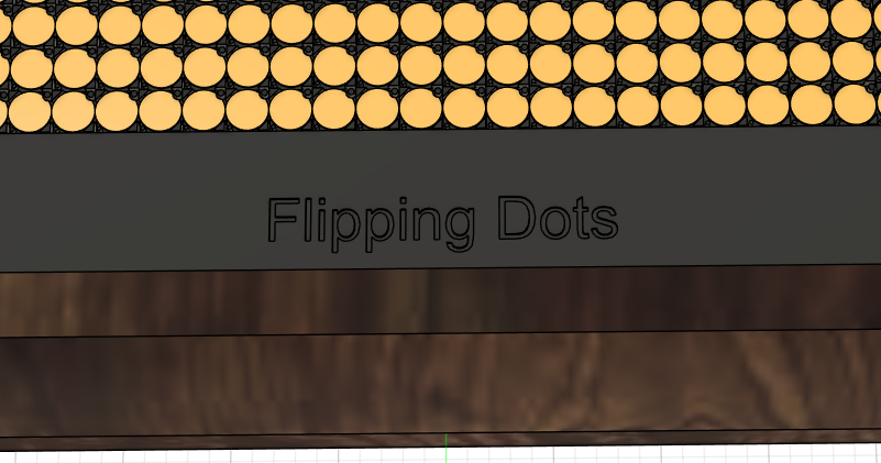 extruded the text using an offset and the cut operation to “engrave” it into the cover
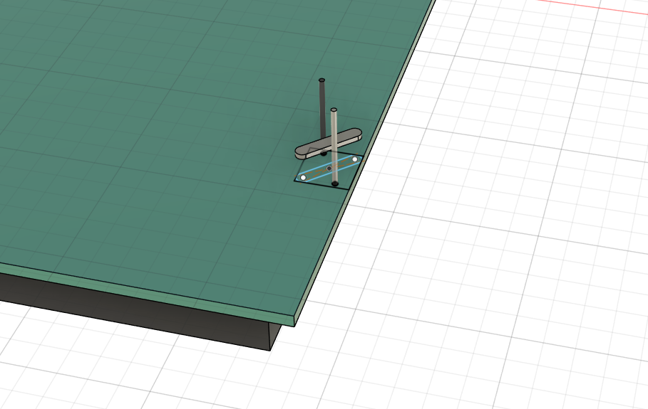
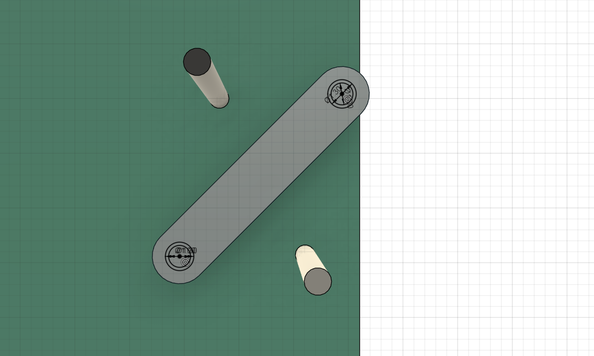
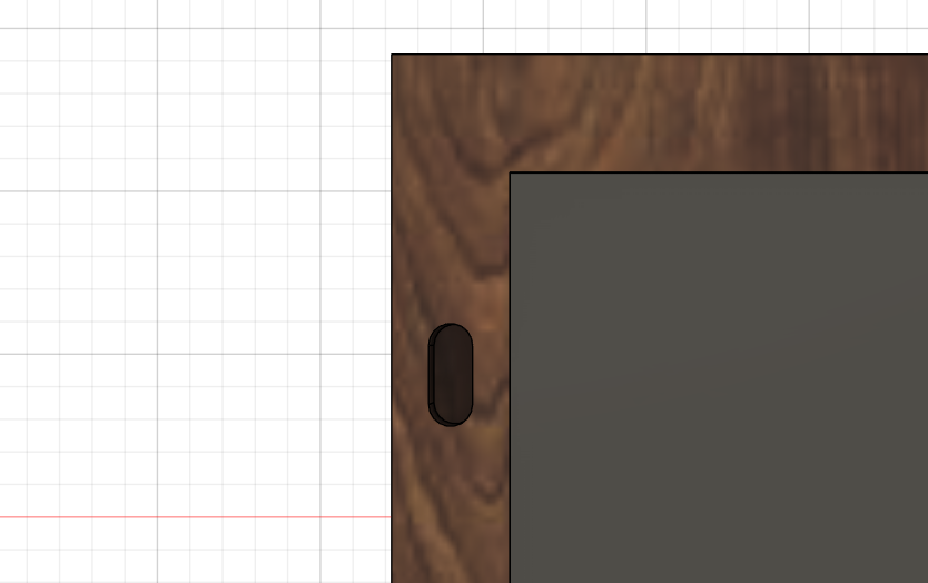 extruded the slot
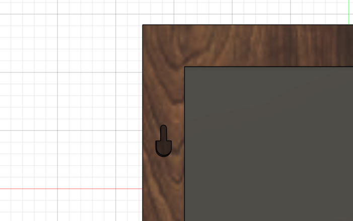
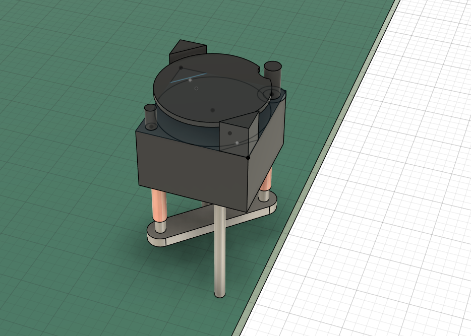
extruded part of the slots outer rim at an offset to create an insert for nails or screws
 did the same on the other side