This weeks assignment was milling and soldering an USB to Serial converter. The board design was provided.
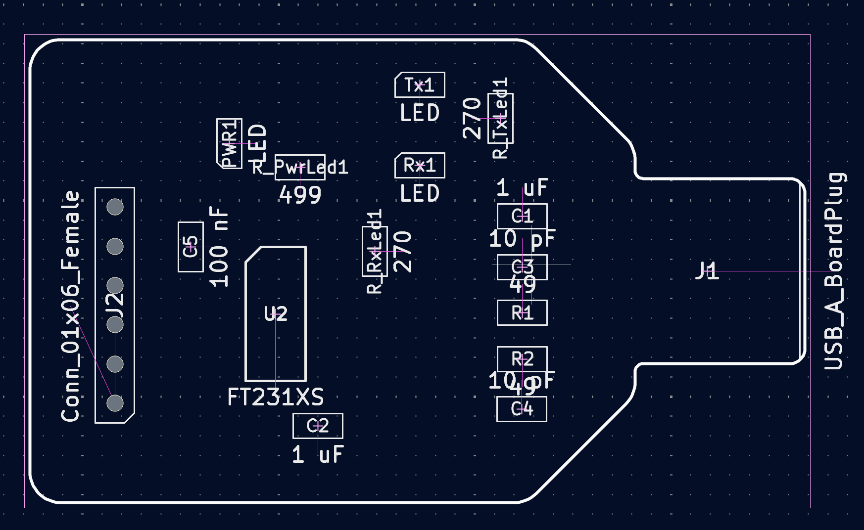
This is the board. Since there were some problems with the mill not every student got to mill their own boards. Because of that this page will focus on the soldering and milling will be explained during the fabrication of the Final Project.
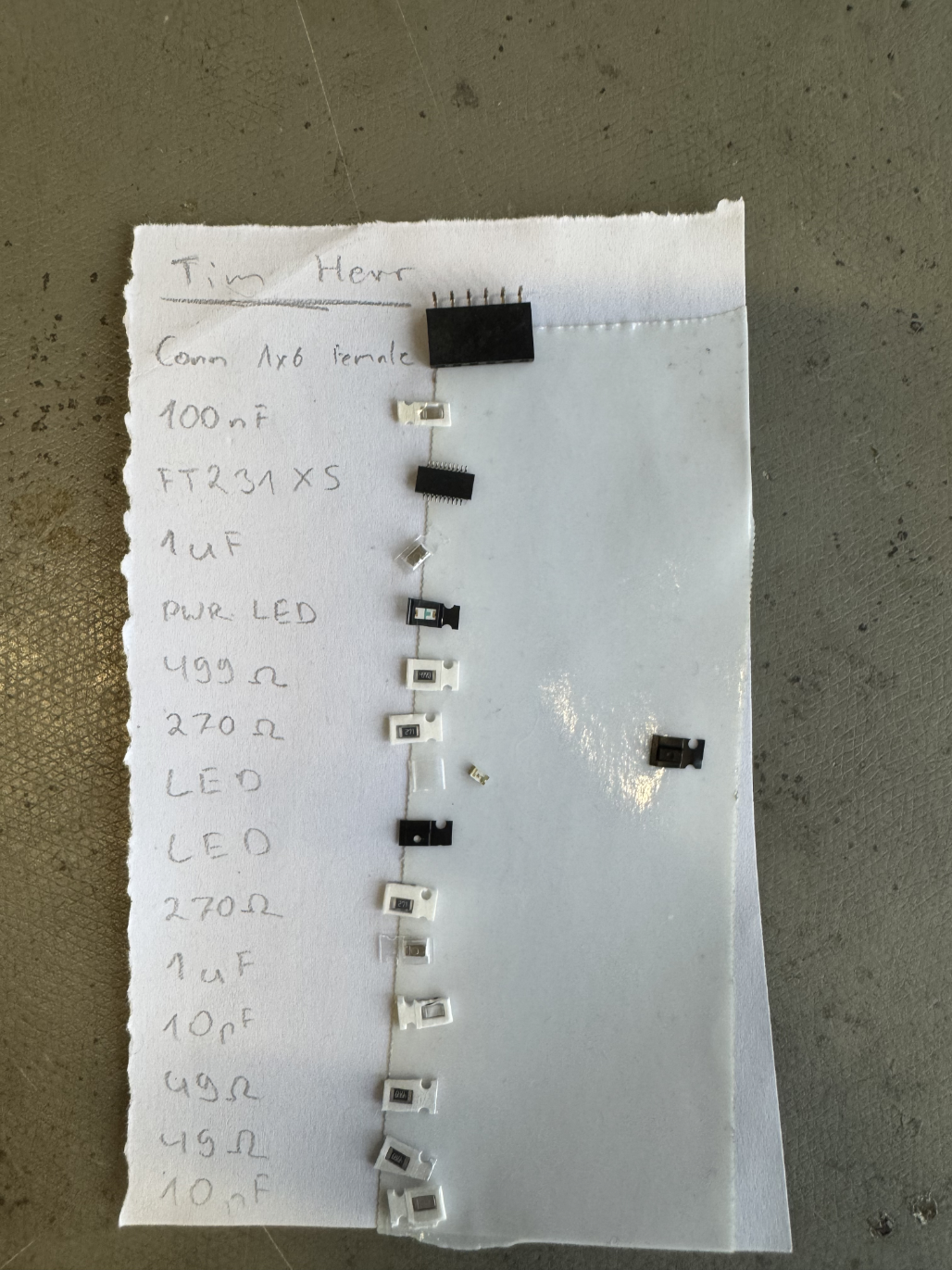
After the board was milled, the first step was to collect all the necessary components.
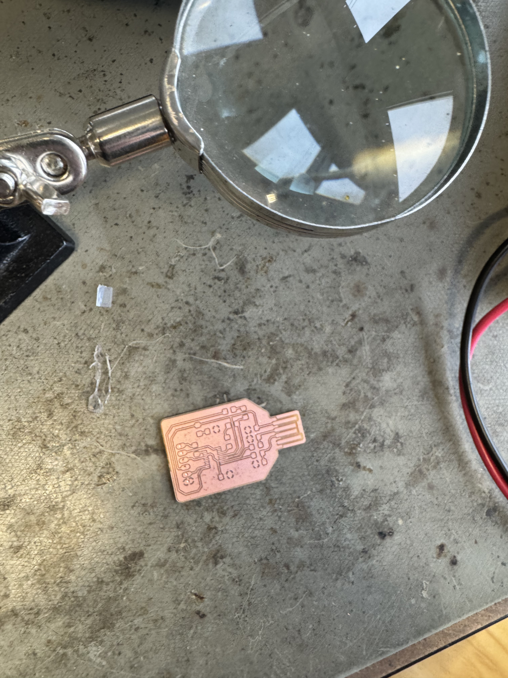
Afterwards it was time to solder. This is the Board before starting.
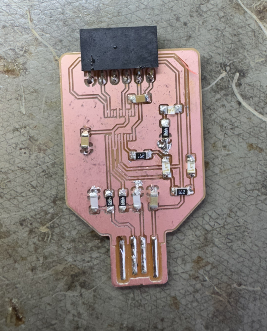
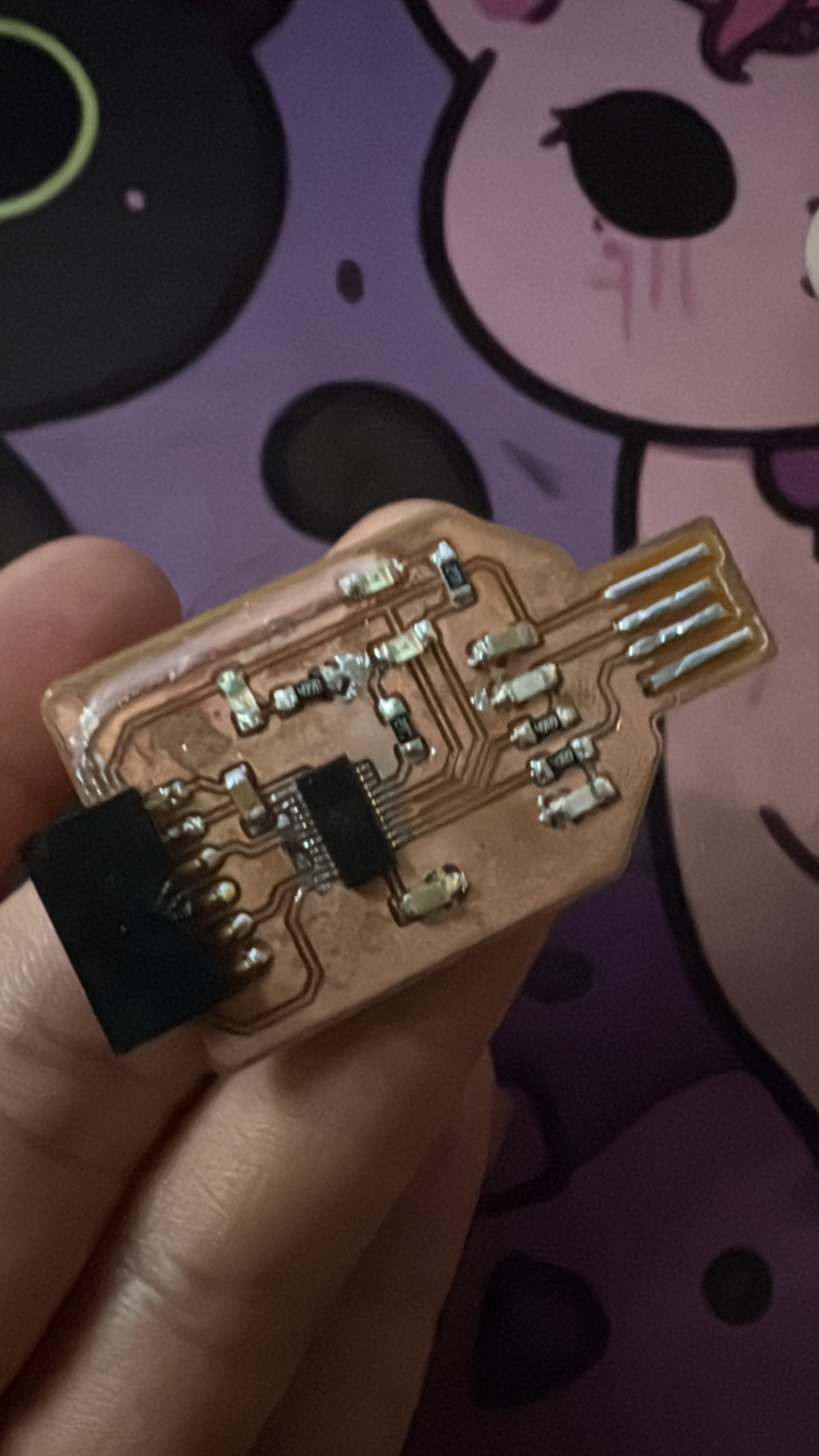
Here is the board soldered, I also added solder to the USB lines to make them thicker which will make the USB connection more stable. The only thing missing here is the micro controller.
Sadly here is where I made a mistake trying to clean up the board using solder wick. In the top right corner of the board, I ripped out the copper layer since it was stuck to the wick.
Since this was not easy to fix I asked Mika for help. He had the Idea of using cable to replace the line, but since that cable couldn’t touch any other connection on the board it had to be isolated somehow. Here Mika chose to use Resin. First He covered the part of the board where the cable would go with some UV Resin. After that hat hardened he soldered and glued the cable onto the board and then covered the top of it in another layer of UV Resin. This actually worked really well.
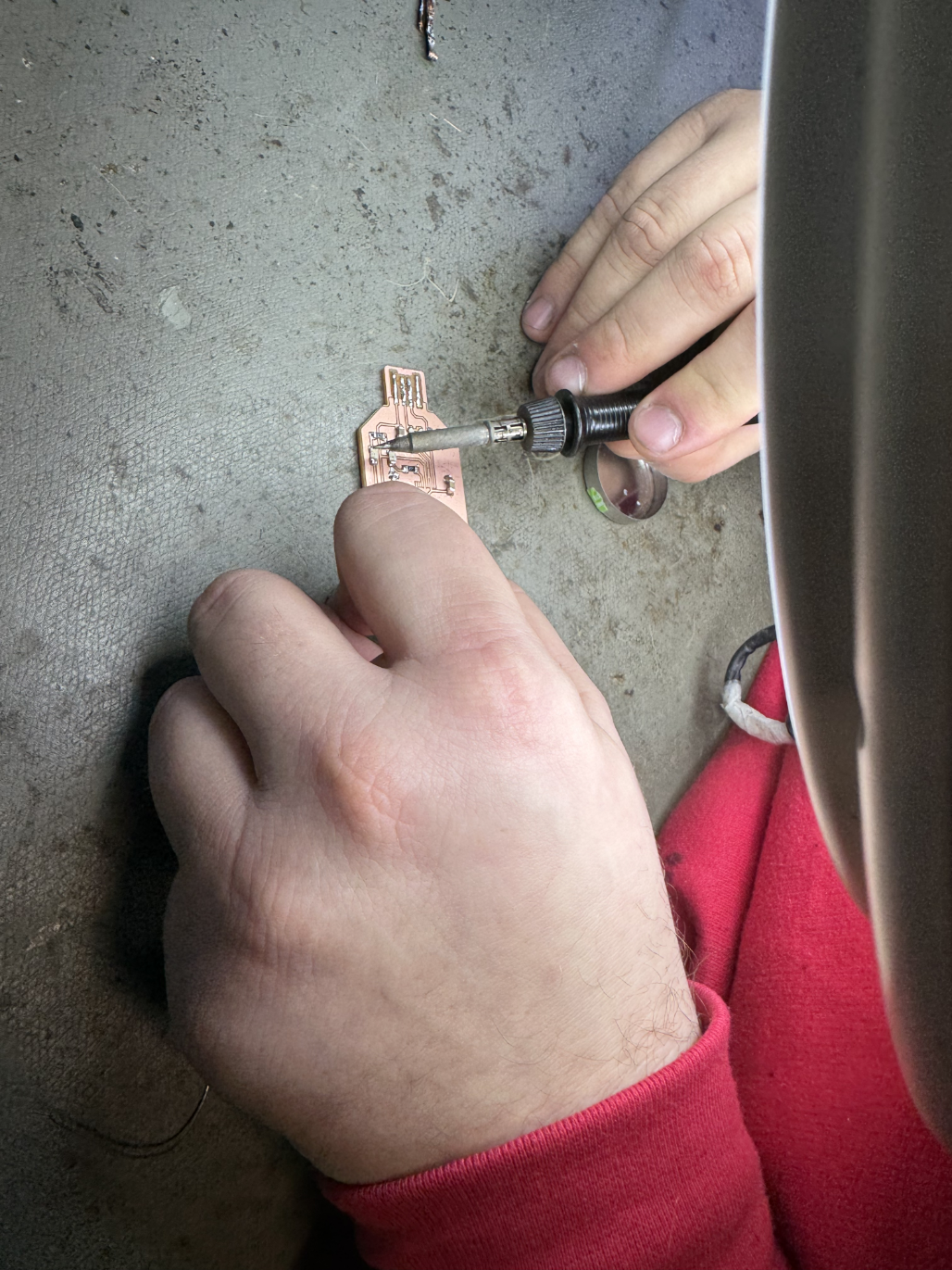
After that I had to solder on the micro processor. Here I used some flux to position the chip and then soldered one side of the processor to the board. After that I soldered the other side. But now both sides were completely covered in solder so I used the solder wick to pull the solder out from between the processor legs to remove any shorts.
After thoroughly testing the board with a multimeter (and fixing some connections), we tested the board by plugging it into a PC and using it to communicate with an Arduino.
Here is the final board: