Poster
 Or view the Poster here digiFabPoster.png
Video
Presentation
This is the presentation I held in front of the class to explain my project to everyone. Everything in it will be explained on this page, it is only included for completeness.
Artifacts
Controller Board KiCad Project (also includes schematic for decoder):
digiFabFinal.zipDecoder Board KiCad Project:
Transclude of digiFabFinal-decoder.zipSpacer Blocks Fusion Archive:
Transclude of flipdot-spacers.f3dCase Stand Fusion Archive:
Transclude of flipdot-stand.f3dCase design for laser cutting:
Transclude of box-all-correct.dxfJoystick case:
Transclude of flipdot-joystick.f3d
The Idea (again)
This is just a quick reiteration of my final project Idea. The full description can be found in Final Project Idea.
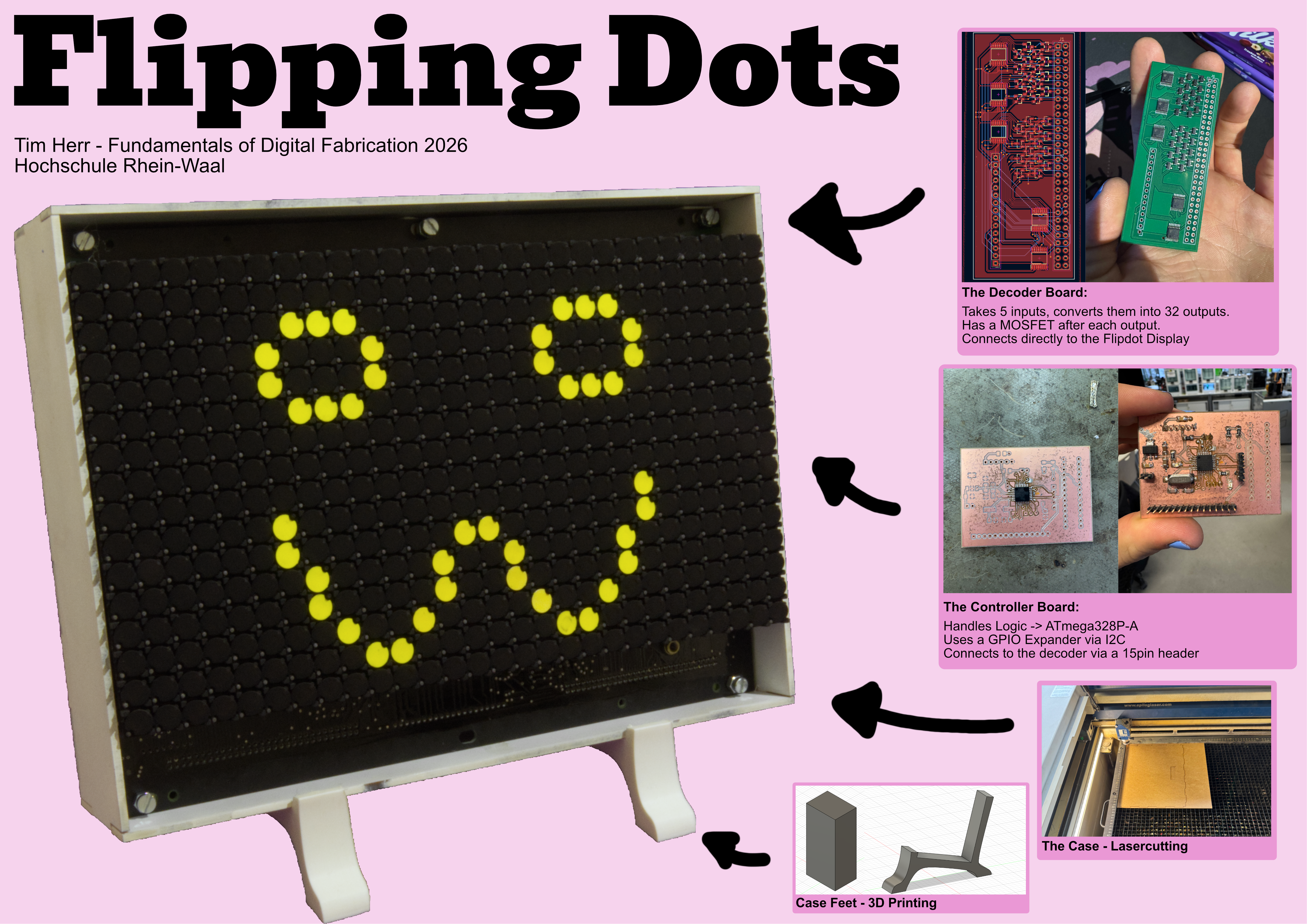
For my final project I wanted to turn an old Flipdot module I had bought off of Ebay into a functional display. This module was produced by the company BROSE and used mostly as a display in busses. Nowadays Flipdot modules are not really produced anymore.
My Idea was to control this display using my own controller board. Then I wanted to include a joystick and make it possible to play snake on the display.
Understanding the BROSE Flipdot Module
The first step was understanding the Flipdot module. This was problematic since I could not find any official documentation online. The only thing I managed to find was this blog by Rainer Radow, documenting the functionality of the module. While it helped me tremendously it was not really exhaustive and I still had to do a lot of testing to figure out how to address my module.
How Does the Module work?
So, in order to understand how the Flipdot module works, we need to understand a single dot first.
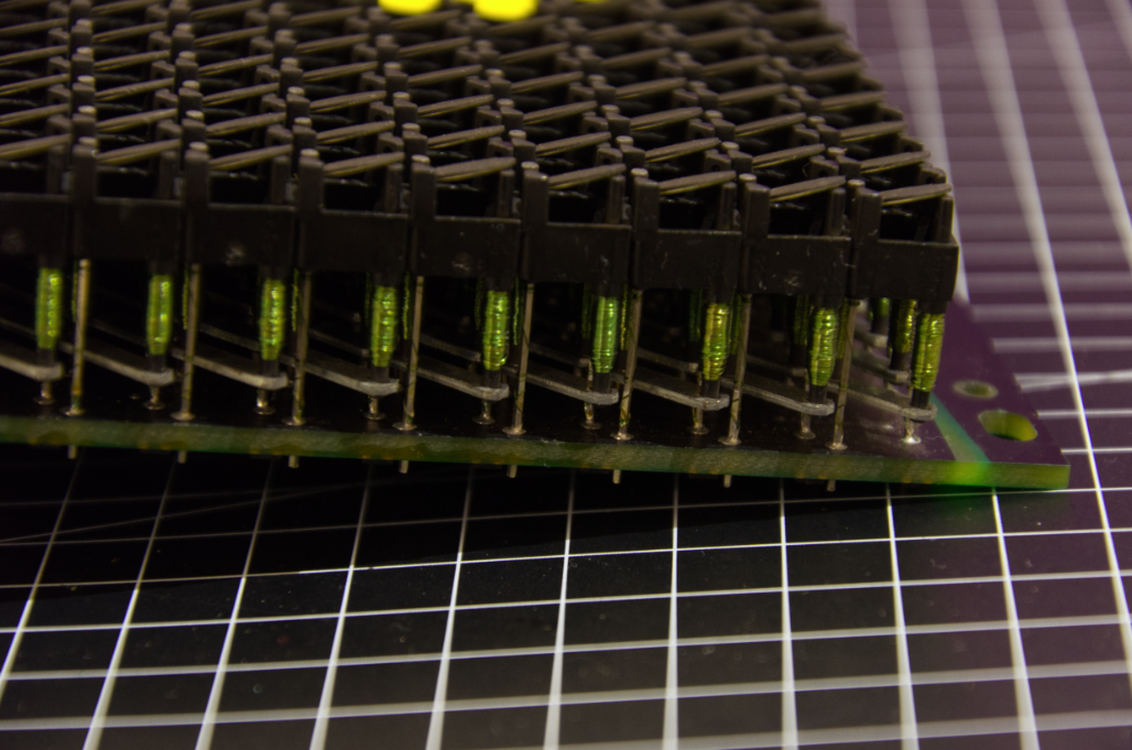 A single dot is made up of three things:
- A magnetic top plate, black on one side yellow on the other
- Two coils with an iron core forming an electro magnet
- Two connections to the underlying board The dot is either yellow or black and stays that way because of the polarity of the electro magnet beneath. In order to flip the dot, the two connections have to be powered to reverse the magnets polarity. It is important to only give a quick impulse to the dot otherwise the coils might be damaged.
The module is made up of 448 dots, arranged into a 16 x 28 matrix.
The individual dots are addressed via rows and columns:
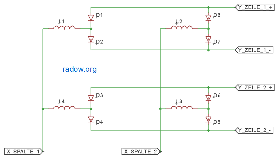 Image from: https://radow.org/flip-dot.php, all rights belong to Rainer Radow
Here you can see how four dots (L1 to L4) are addressed in the matrix. Every column (X_SPALTE) has one connection and every row (Y_ZEILE) has two. Each dot has two diodes making sure the signal flows from row to column and not between the two row connections.
Two flip a dot you have to connect one of the rows and the column. This way the polarity of the signal can be switched depending on the connected row and the polarity of the column.
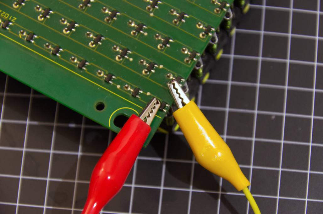 This is me testing one specific dot using my lab power supply to control the voltage. At least 9 Volts are needed for the dot to flip, 12V produce a good, fast flip. According to Radow, 24V were used in busses and such.
How to Address the Module
Now that we understand the basic functionality of the module we need to discuss how to address it properly. Beside the matrix itself the module also the following other components:
- A 60pin Connector
- Comparator logic for module selection
- A Chip to drive the columns These components need to be understood to address the module correctly. Radow’s blog helped a lot with this, but I also needed to test many of these components myself to actually understand them.
The Comparator Logic
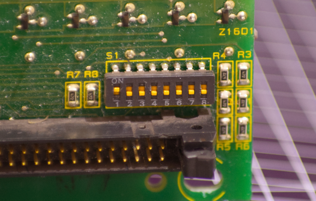 The Comparator can be neglected in this case. It was used to determine which module should be addressed when they were placed in series. In my case the first switch needs to be off and everything else should be on (according to Radow’s blog and my testing).
The FP2840 Chip
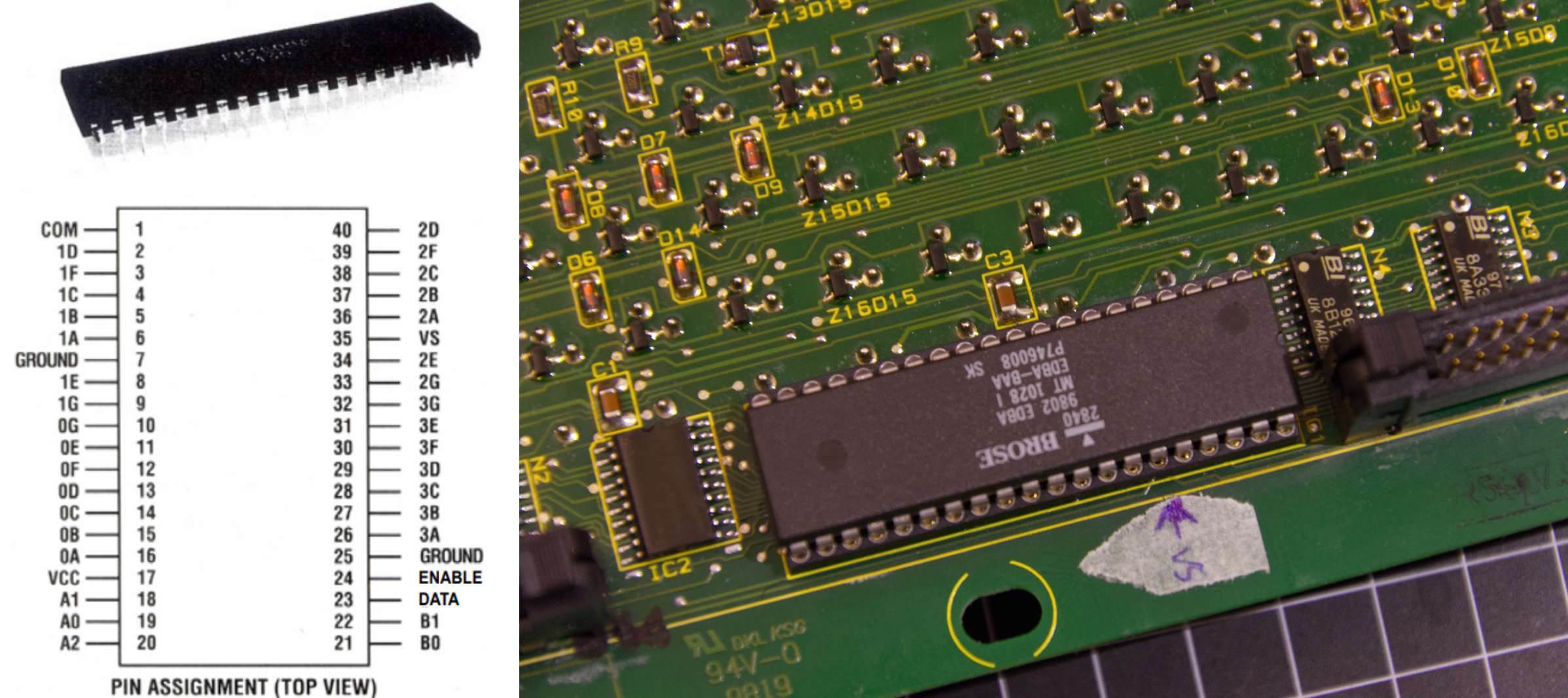 This chip controls all 28 columns of the display. It is a “one of 28” decoder and was used to drive 7-segment displays. Depending on 6 Inputs It provides a positiv or negativ output on one of the 28 output pins. The truth table can be found in the datasheet: fp2800-datasheet.pdf.
According to Radow’s blog, this chip is at risk if the electrical impulse is not timed correctly since it switches the actual 12V driving the dots. Because of this I elected to test the board without the chip, rather switching with jumper cables instead.
The 60pin Connector
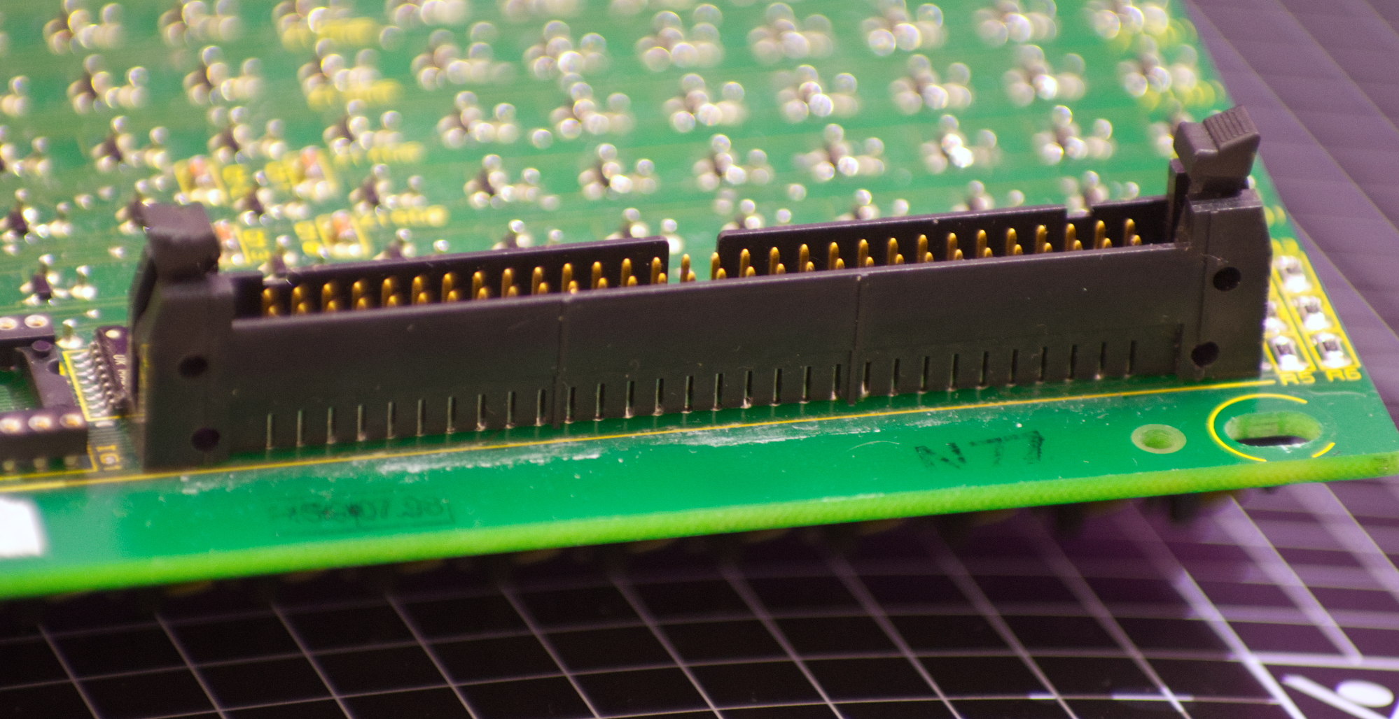 This connector is what I have to actually address to drive the display. Most BROSE modules have two, one input and one output to drive them in series. If there are two, the left one is the input connector.
Most of the pins on this connector are used to address the rows of the display directly. There are 40 total connections for 20 possible rows since each row has one negativ and one positiv connection (as was explained above How Does the Module work?). My module only has 16 rows so 8 pins are actually not connected.
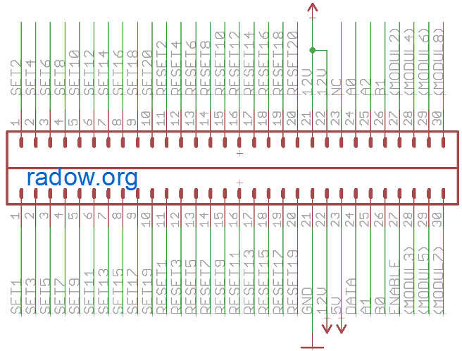 Image from: https://radow.org/flip-dot.php, all rights belong to Rainer Radow
The other pins are used to address the chip and the comparator logic.
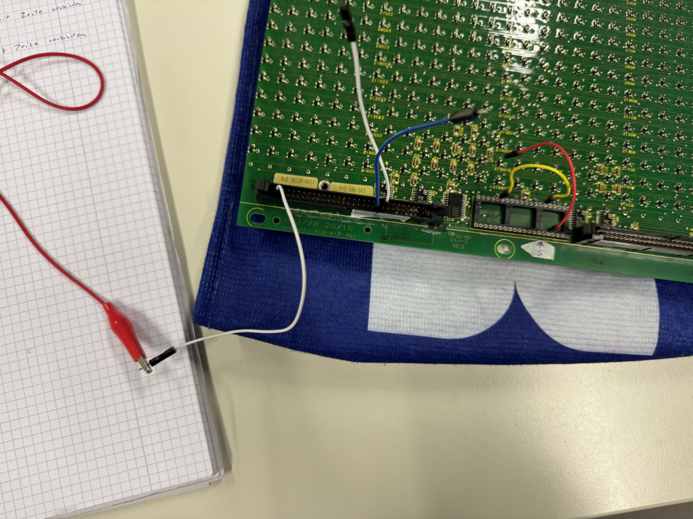
Actually Flipping Dots (Testing)
To actually flip a single dot (while not using the chip), you need to do the following:
| 60pin Connector | Chip | |
|---|---|---|
| From black to yellow | 12V connected to SET-X GND connected to GND | GND connected to row |
| From yellow to black | GND connected to RESET-X 12V connected to 12V | VS connected to row |
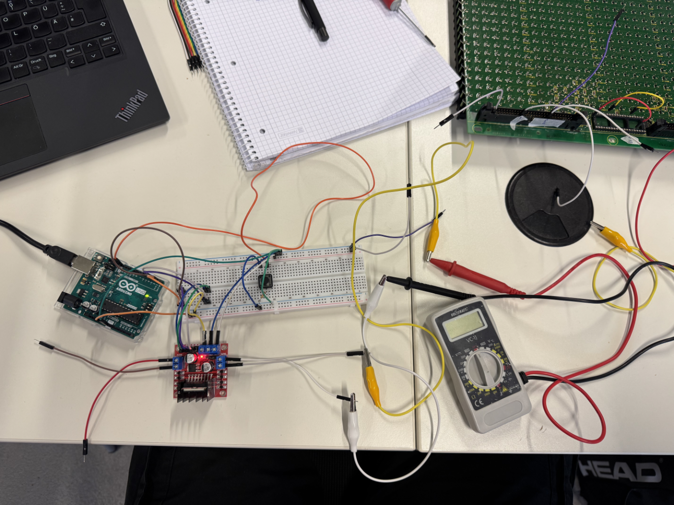
| But how could I achieve this with a microcontroller? There needed to be something to switch the 12 Volts and GND. For the initial tests Ahmed provided me with a Motor Diver IC that was basically a double H-Bridge: | ||
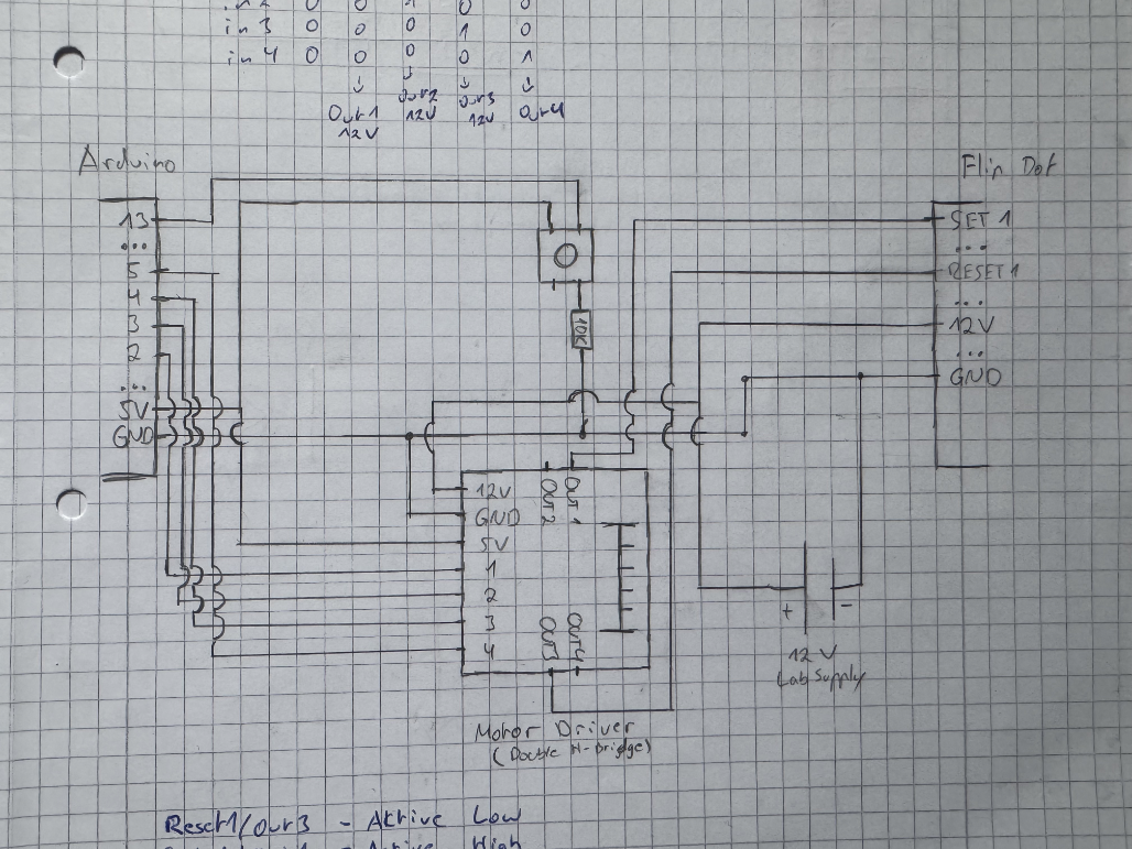 | ||
| Testing with an Arduino, I first drew this schematic. The Arduino addresses the motor driver via four digital pins and a button is connected to another digital pin. The 12V power supply is the lab supply from the FabLab. This is then connected to the 60pin Connector of the Flipdot display and the chip is replaced with a jumper wire: | ||
 | ||
| The Arduino can then detect a button press and configure the motor driver to output 12V / GND depending on the state of the dot. The only manual input necessary is switching the connection of the jumper wires replacing the chip. |
Since I this setup using the motor driver only let me control two rows maximum I elected to test using MOSFETs.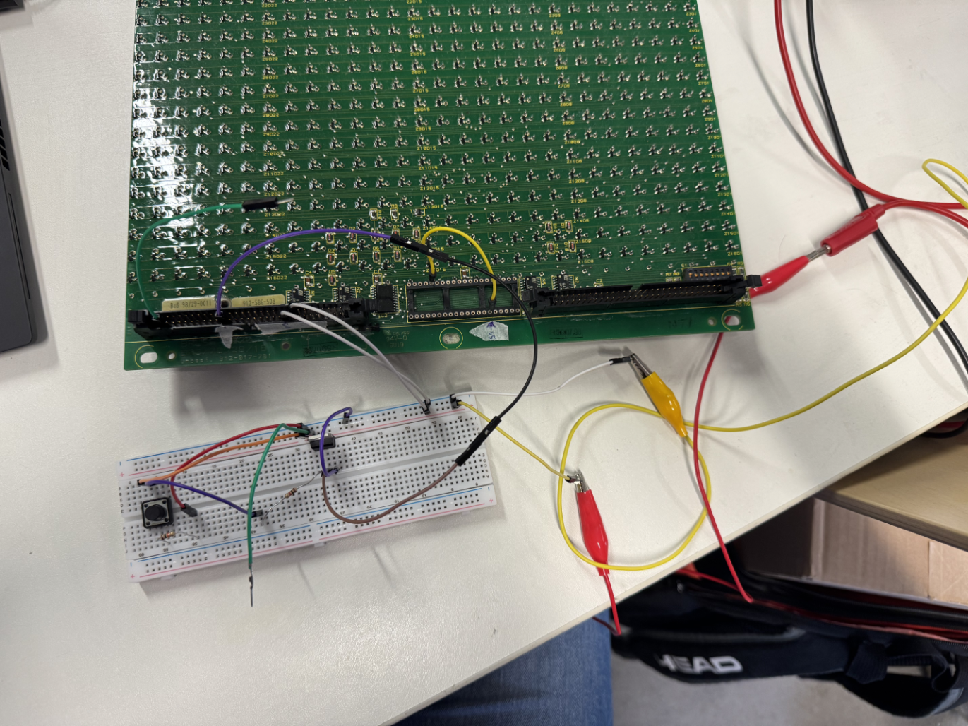 The Lab only had NPN-MOSFETs meaning that I could only connect GND to a specific pin. Because of this I set my test up to connect GND to the Reset pin when I press the button. This allowed me to flip a dot from yellow to black on button press. It also proved that I could use MOSFETs to address the Reset pins. I would only need PNP-MOSFETs to address the Set pins and everything should work out.
Designing the Boards
Now that I have tested the Flipdot module with a MOSFET it is time to design my own board. I have decided to split my design into two, one board for the logic and one to address the rows of my display. This second board needs to have 32 MOSFETs and after consulting with Ahmed I decided to order it off of JLCPCB already fully assembled to save time.
Controller Board
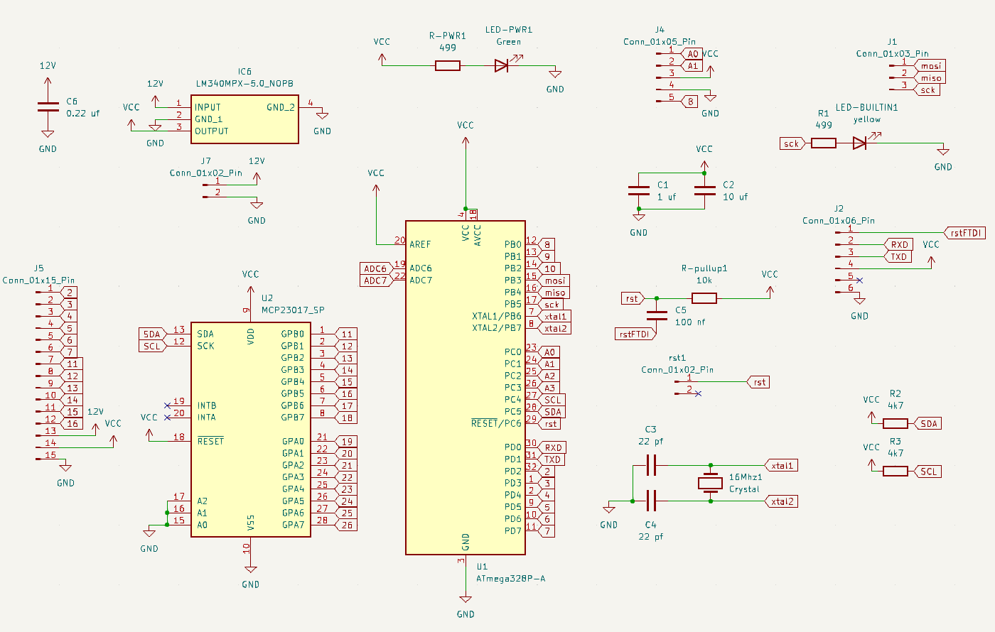 The controller board is going to do the computation and handle the logic of the whole project. It needs to connect to three external components:
- A Computer via the Serial to USB interface we built in Week 7
- The Joystick
- The Decoder Board
Another thing the controller board needs to handle is power. Since the dots need 12V to flip, the board uses a linear voltage regulator to step 12V down to 5V. This means that the 12V can be passed to the decoder board and the controller can use the stepped down 5V eliminating the necessity for the lab power supply.
The chip we are using for this class is the ATmega328P-A which has 9 digital pins. But my board needs more than that:
| Pin Count | Usage |
|---|---|
| 1 | Joystick Button |
| 6 | Custom Decoder Board |
| 6 | Chip on the Flipdot module |
| Because of this I elected to use a GPIO expander. This IC is addressed via I2C and provides 16 additional digital Pins. |
The full bill of material for this board can be found here (exported from KiCad Project):
Transclude of digiFabFinal.csv
 The routing for this board was pretty challenging, because of this I chose to use two layers, the front and the back of the board. This meant I had to use VIAs, but more on that in Manufacturing the Controller Board. But because of that I managed to fit all of my components very close together avoiding wasting too much material.
The full KiCad Project for this Board is linked above, in Artifacts.
Decoder Board
My decoder board needs to do one thing: address the 32 pins for the rows of my display. I need to be able to have all the Reset pins unconnected or high and all the Set pins unconnected or GND. Then I have to be able to pull one specific Reset pin down to GND or one specific Set pin up to 12V.
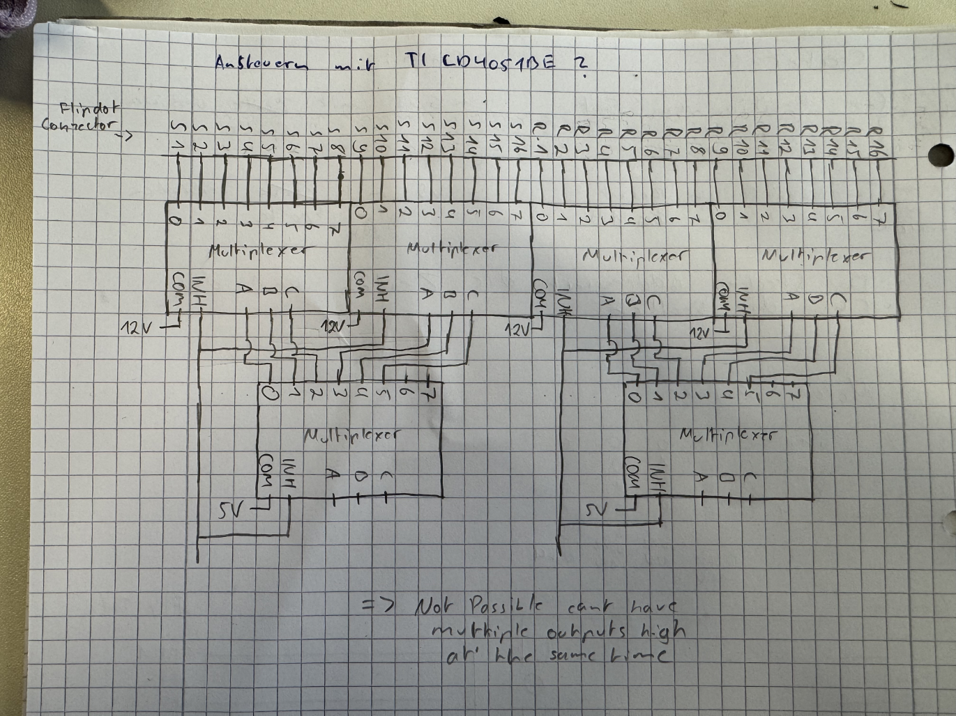 At first I decided I should create the board using six Multiplexers. This would allow me to address 32 pins and provide them with either GND or 12V. But with this design it is not possible to have multiple outputs high at the same time, which would be necessary for the Reset pins.
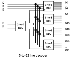 Then I found this graphic explaining how to create a 5 to 32 line decoder and decided that I would need to implement this logic if I wanted to address my display. This allows me to address all 32 pins individually and only uses 5 digital pins of the ATmega. I would need to have a MOSFET behind each output of the decoder but that is not a problem.
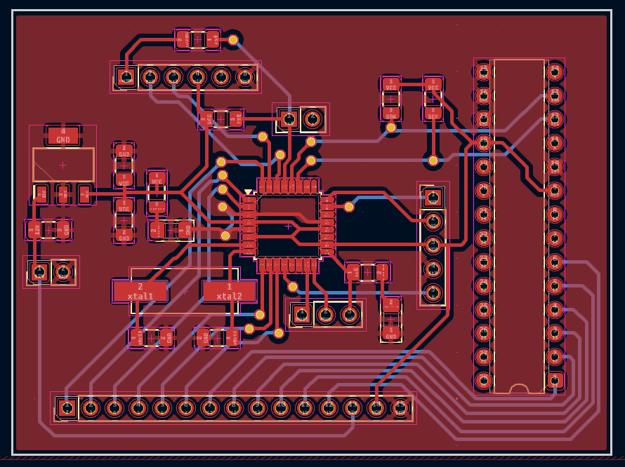
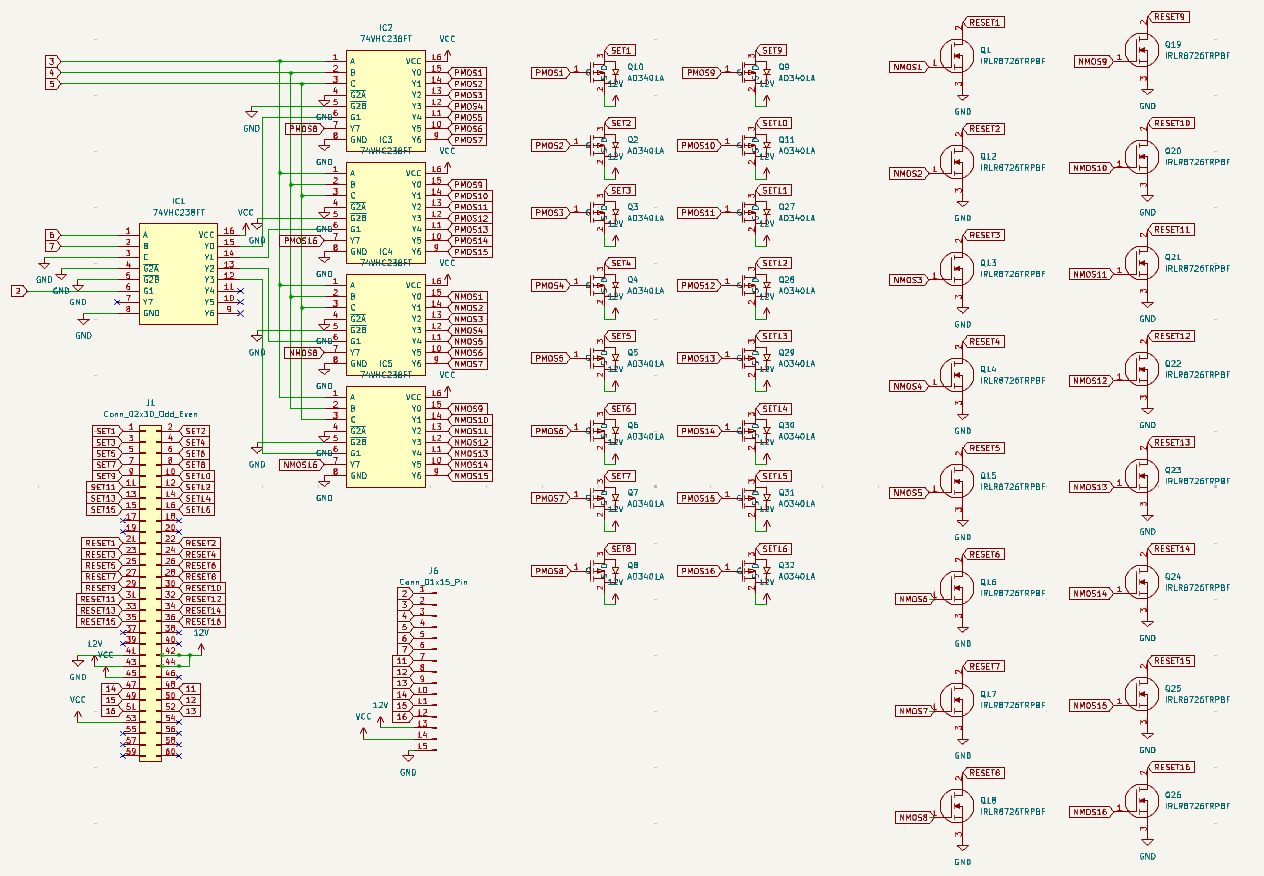 This is the design I came up with according to the diagram above. I am using five decoder ICs. Behind each output is a MOSFET, 16 are P-Channel and 16 are N-Channel. This allows me to address all 32 pins of the Flipdot display.
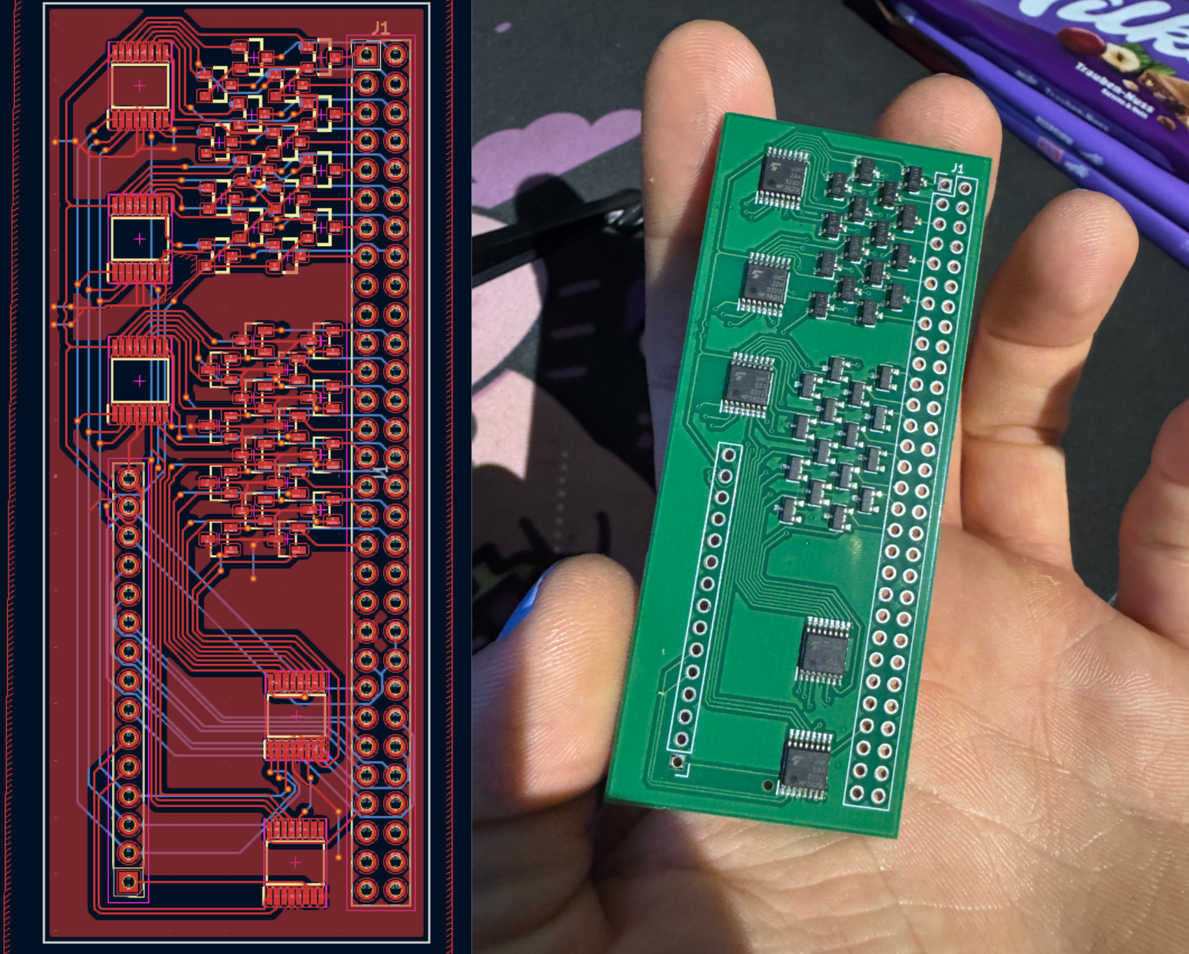 This is the resulting PCB, I also used two layers to make routing simpler and then ordered it off JLCPCB.
The full KiCad Project for this Board is linked above, in Artifacts.
Manufacturing the Controller Board
After I had finished designing the Controller Board it was time to actually mill and solder it. For this it was important to have selected the correct track width and via diameter for the machine in the FabLab otherwise manufacturing the board would not work.
Milling the Board
First I exported the production (Gerber) files in KiCad. I then went to the machine and opened them there in the Milling Software. Then I placed the material onto the milling bed, taped it down and positioned the circuit design within the software so that it fit onto the material (this was done using the tools as markers where the material was). After that I chose the material to be milled and the tools for the different operations. Then I started the Board Production Wizard.
The first step was to select where to place the fiducials that would allow flipping the board correctly. Then the mill made a test cut and I needed confirm the offset it calculated from that. After that I could start the milling process. This is the start of the milling process, the machine begins by drilling the wholes for the through hole components.
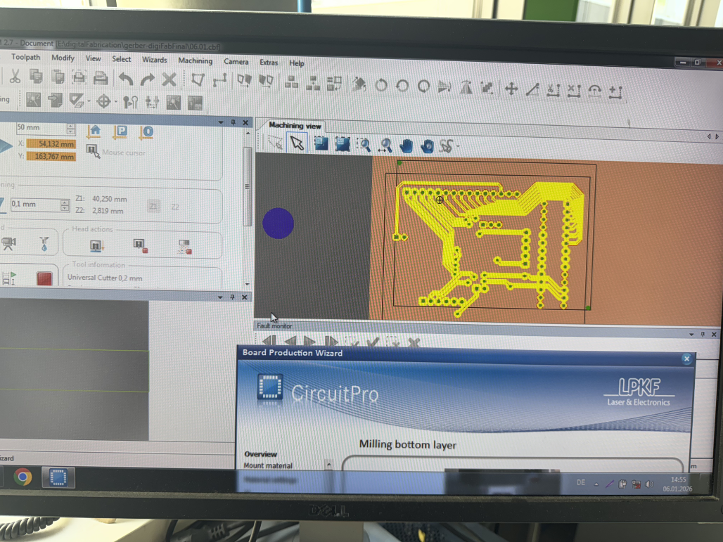 This is the milling progress viewed in the milling software.
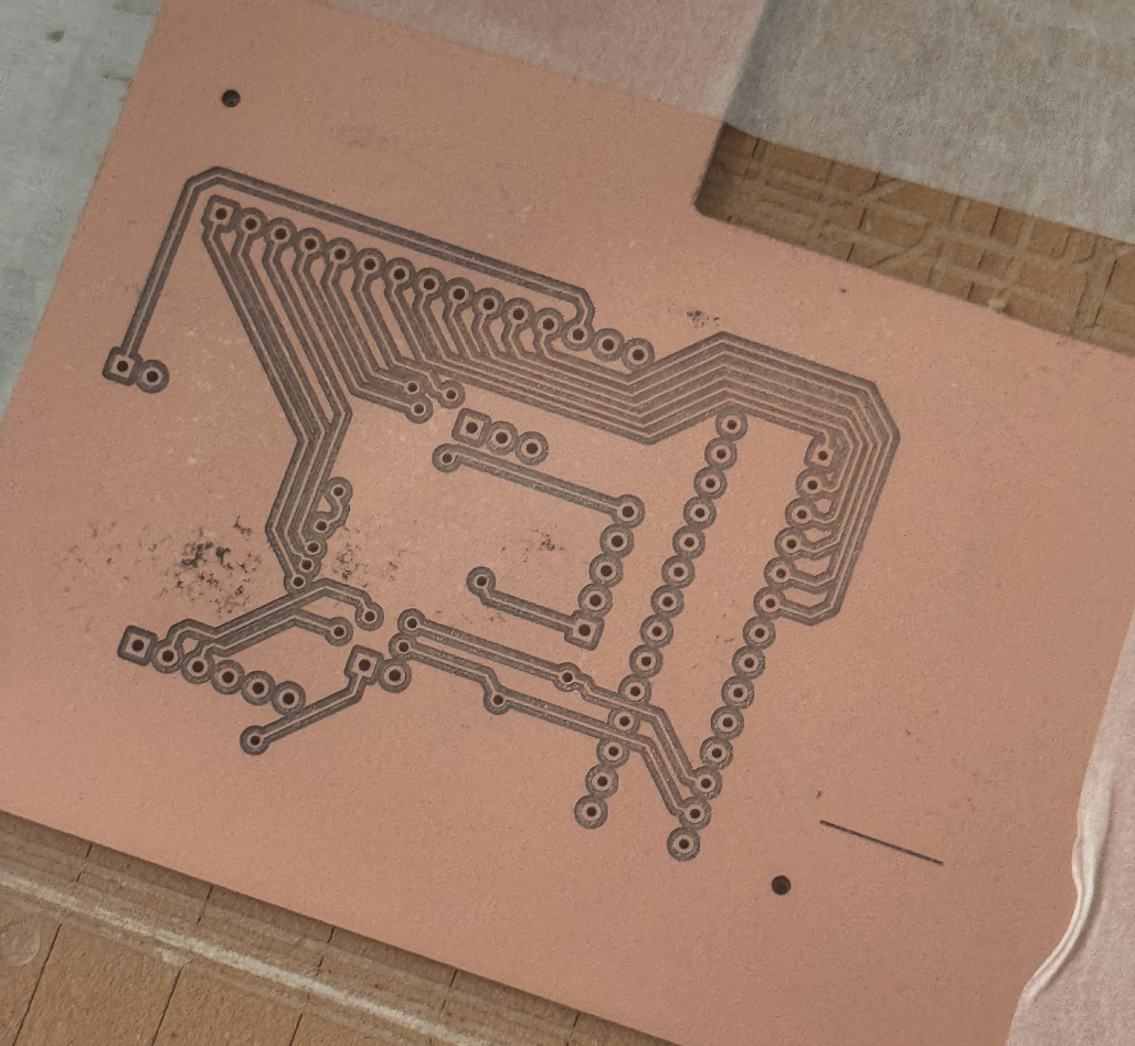 This is the result for the first side of the PCB, now I had to flip it and let the machine reorient itself using the fidicules.
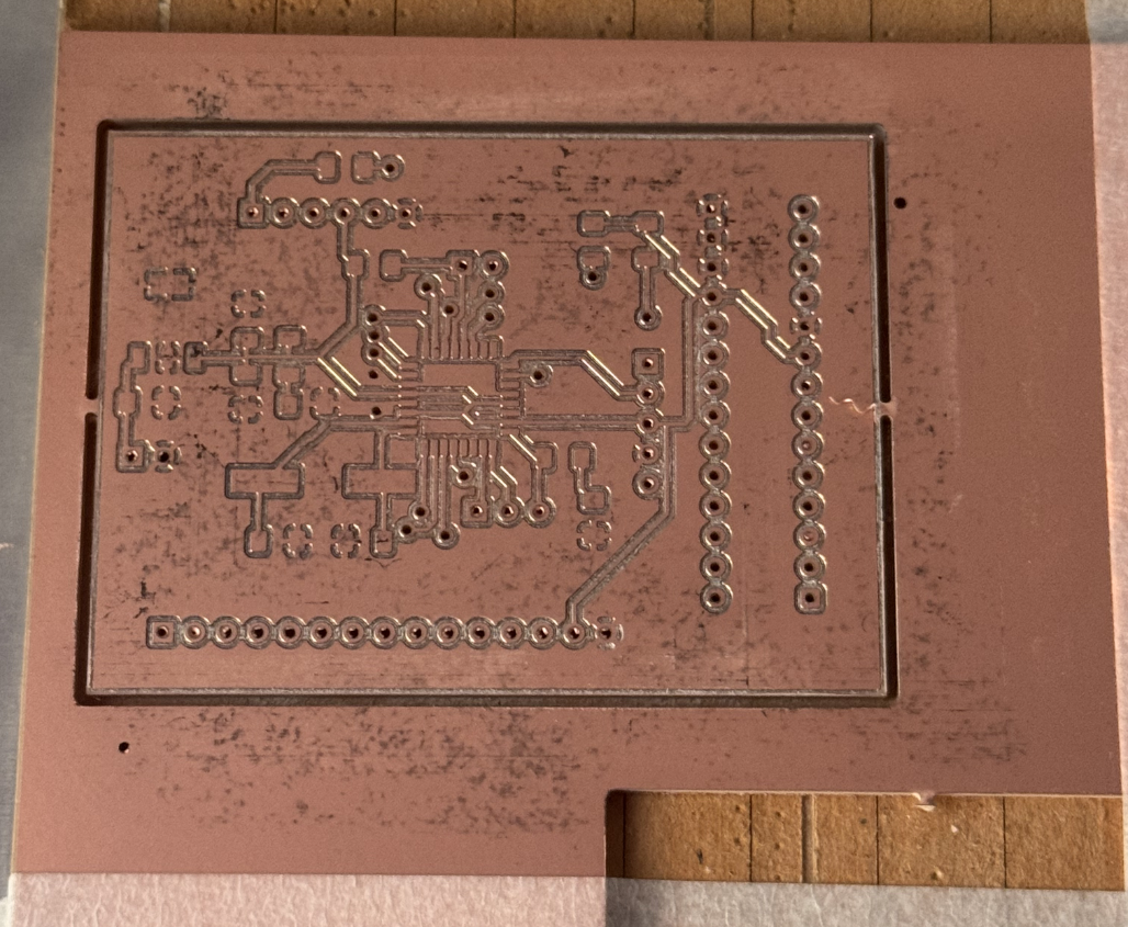 And this is the finished PCB.
Adding the VIAs
Now that the PCB is milled, it is time to put in the VIAs. These are needed to establish connection between the front and back side of the PCB.
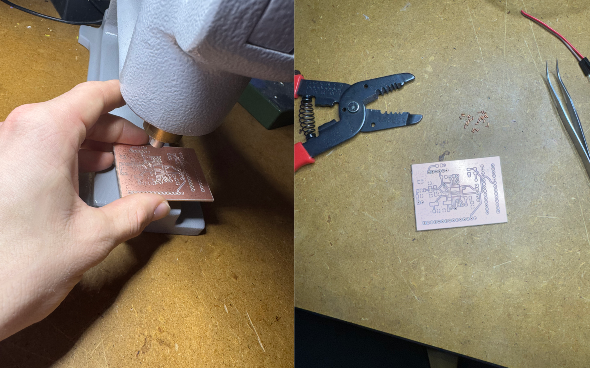 Placing the VIAs manually requires first aligning them with the drilled hole and then pressing them with the machine on the left. This also crumples the VIAs so that they can not be removed again.
After that I tested the connection between the two sides and added solder where it was necessary.
Placing the VIAs manually requires first aligning them with the drilled hole and then pressing them with the machine on the left. This also crumples the VIAs so that they can not be removed again.
After that I tested the connection between the two sides and added solder where it was necessary.
Soldering
Now the board is prepared for soldering.
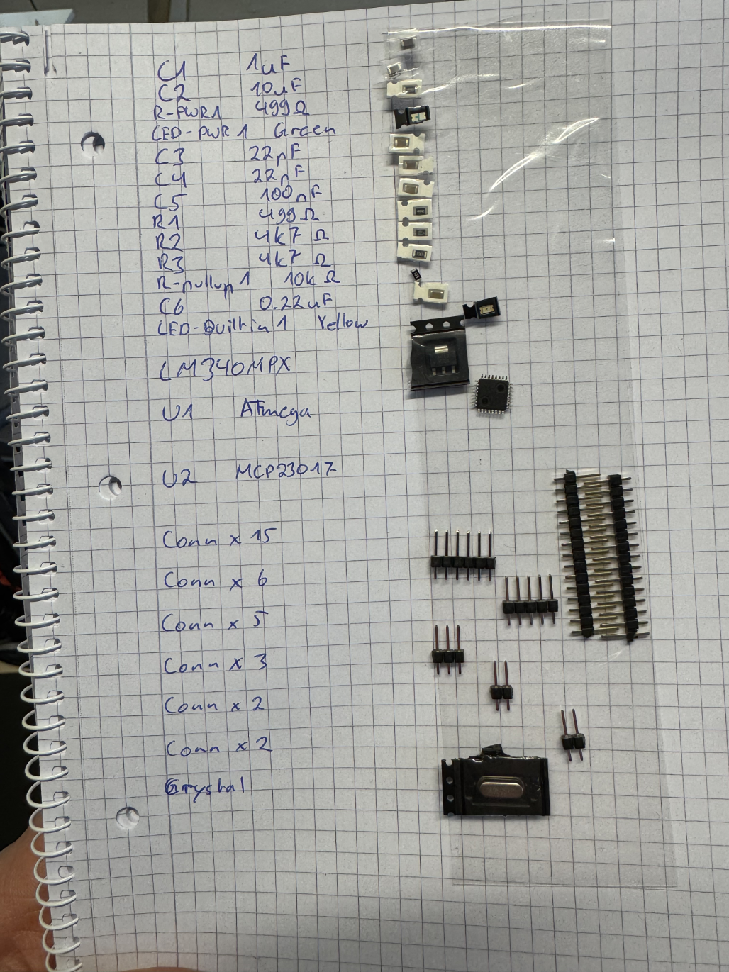 First I assembled my components. Then I got started soldering.
.png) I started by soldering the Chip onto the board since this is definitely the hardest part. After I managed to install that correctly I soldered everything else. While soldering I tested the connections with my multimeter. As you can see the GPIO Expander had not yet arrived, I soldered that at home.
I started by soldering the Chip onto the board since this is definitely the hardest part. After I managed to install that correctly I soldered everything else. While soldering I tested the connections with my multimeter. As you can see the GPIO Expander had not yet arrived, I soldered that at home.
The Joystick
Another component of the project is the joystick. I had picked out a joystick and exposed 5 pins on the controller board according to its specifications. But then Jan offered me an old joystick he still had on hand which allowed me to start testing earlier so I took that one.
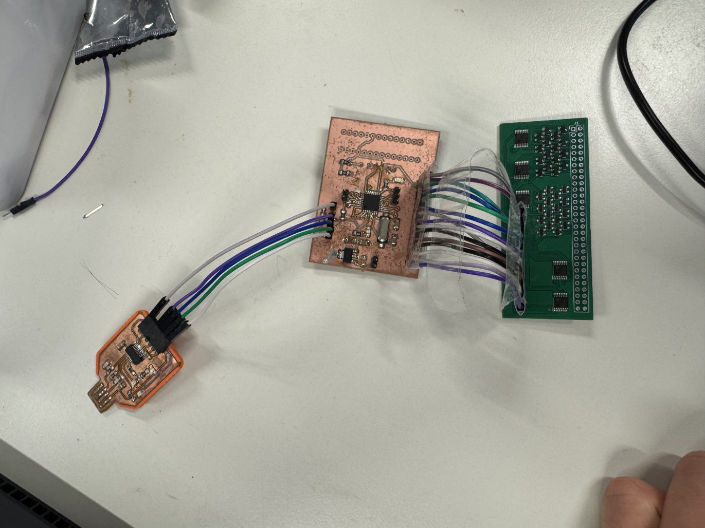
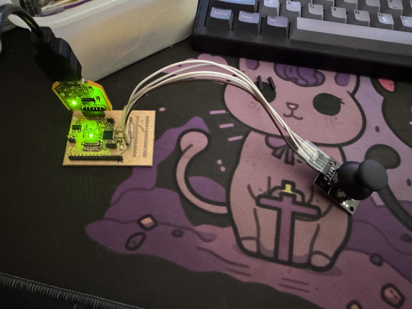 Here I have connected the Joystick to the controller board using the 5 exposed pins. I then tested the joystick and while the two analog outputs for the stick position worked perfectly I noticed that the button press did not register. I then found out that this was because this joystick did not have an internal pull down resistor.
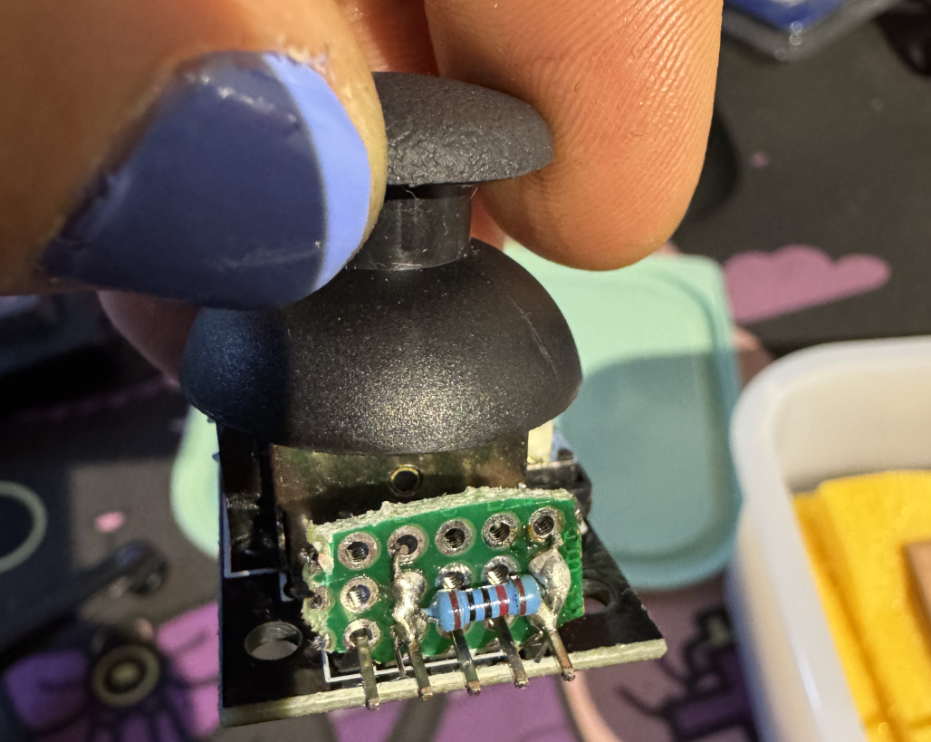 I took the liberty of installing one myself using some parts I had lying around at home and after that the joystick worked flawlessly.
I then went ahead and designed a case for the joystick in Fusion360
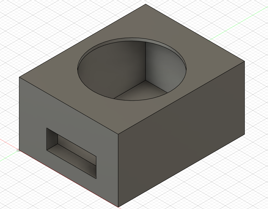
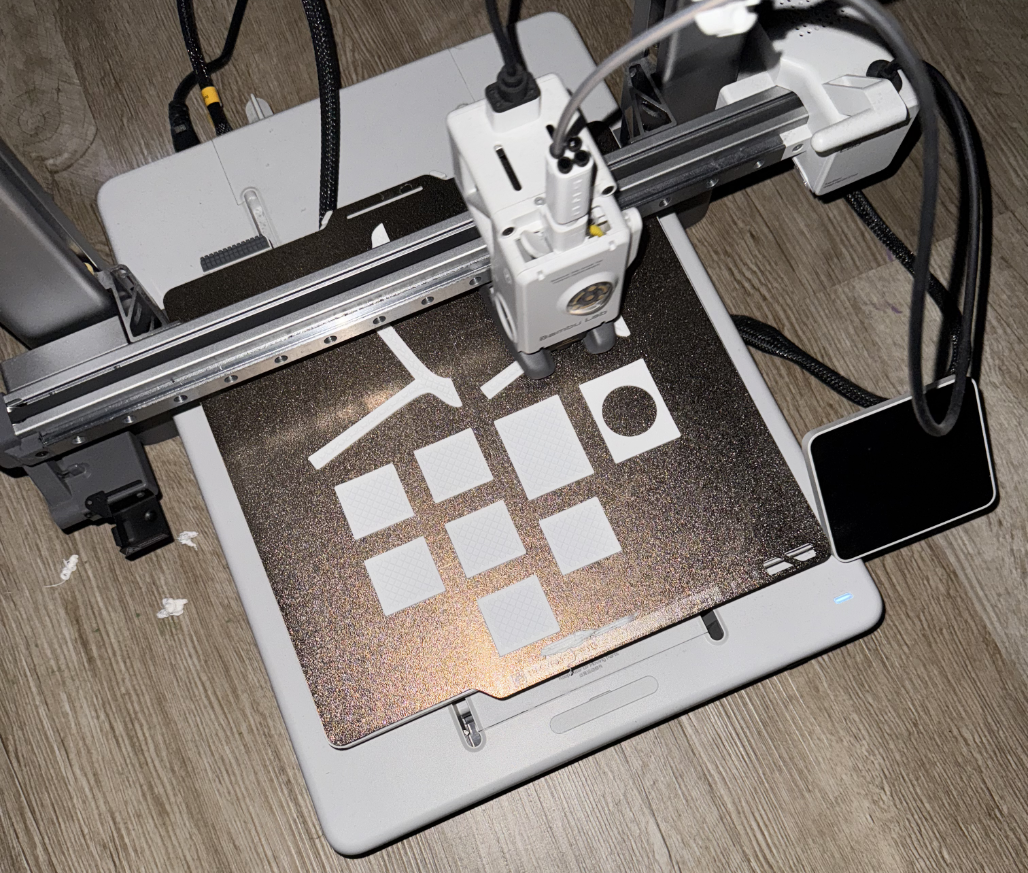
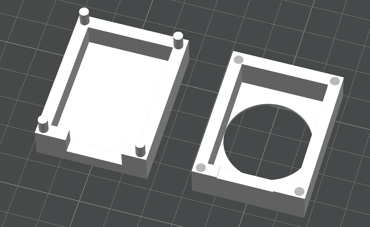 To 3D print the case I split it in two in the Bambulab Slicer. I then printed it at home on my Bambulab A1 and assembled it in the Fab lab, using the Dremel widen the holes to fit the pins.
 I had to remove some of the cover so that it would not hit the case.
The Case
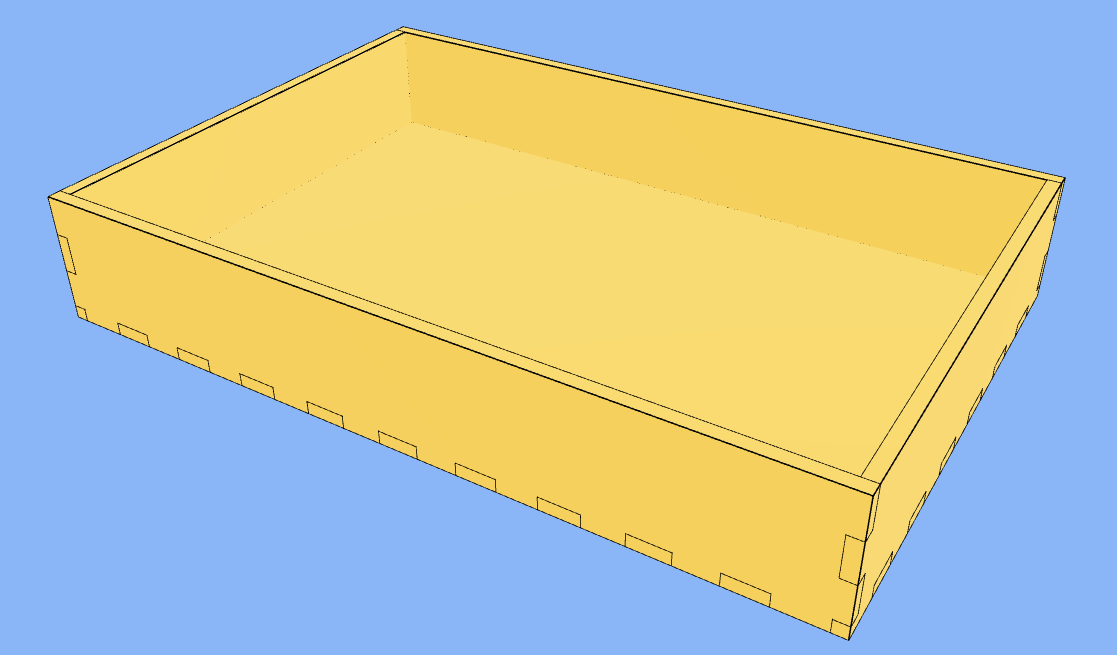 With all other hardware components finished I set out to make the case. It is based on a basic box from Makercase (https://www.makercase.com/basicBox) that fits the display with enough space beneath for the other hardware components. I also added a slit to the back plate to accommodate the power supply and joystick wires.
I then Laser cut the box on the large laser cutter in the Fab Lab.
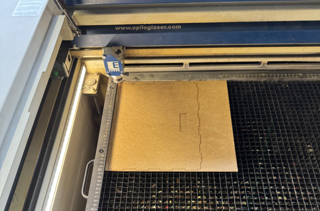 This is a first test cut of the backplate.
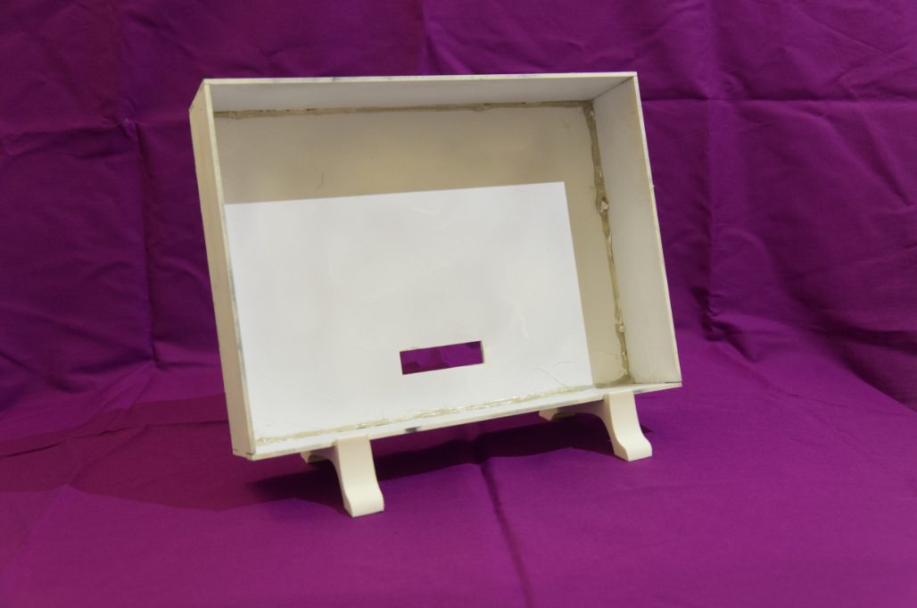
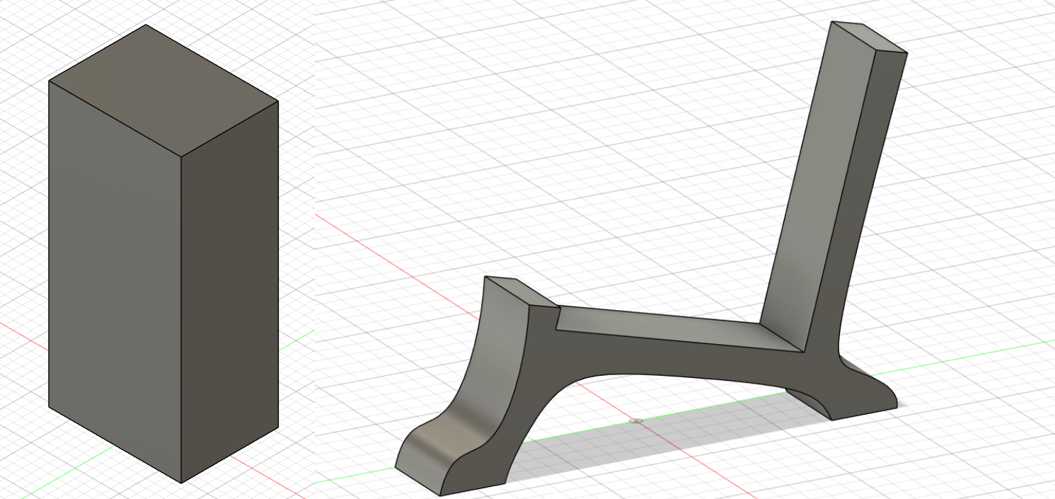
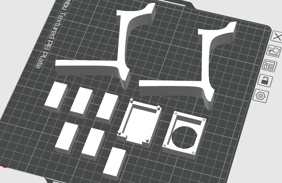
After that I set out to create spacers that would hold the display up and allow for space underneath where the circuits are mounted. These are just blocks with the correctly measured dimensions. I also created nice angled feet for the case so that it could stand upright.
All of this was then imported into the Bambulab Slicer and printed at home.
The Code
The following code omits most of the actual implementation to highlight the whole functionality, here is the full code:
Transclude of digiFab_Final.ino
#include <SoftWire.h>
... // a lot of variable setup

void setup() { ... } //pinMode setup and configuring GPIO Expander for output vie wire

void loop() {
  if(isFlipping && millis() - flipStart > flipDuration) {
    isFlipping = false;
    resetFlipLogic();
  }

  if (buttonPressed()) {
    flipADot();
  }

  handleJoystick();
}

//uses the GPIO Expander to flip a dot to black or to yellow
void flipADot() { ... }

// resets the signals to the decoder board so that there is only
// an impulse to the flip dot module
void resetFlipLogic() { ... }

// checks if a button is pressed returning true or false
bool buttonPressed() { ... }

// checks joystick potentiometer inputs
void handleJoystick() { ... }

// helper for checking joystick inputs
void resetLastStickInputs() { ... }
This was the basic structure of the first code draft I wrote. I wanted to be able to “select” a specific dot on the display using the joystick and then flip it by pressing the joystick. The full code has a lot of state needed to debounce the button and handle joystick input correctly. Sadly, because of different hardware problems this code never worked.
Problems
As you might have noticed my final product can not play snake. In the following I will detail the different problems I encountered while developing this piece and how I tried to fix them.
The GPIO Expander
The first thing I noticed was with the GPIO Expander. After it had finally arrived I soldered it on at home and wanted to test it. But I could not establish an I2C connection. I started debugging this and found that it advised to install a small capacitor right before the VC pin of the expander.
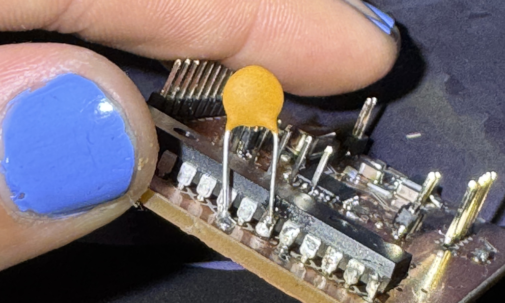 Luckily I had one lying around, but sadly this did not fix the issues.
After a lot of investigating I noticed that I had somehow swapped the SDA and SCL pins on the ATmega. While I could have crossed them using some wires and a knife, I was to afraid to ruin the board. Thus I elected to use the SoftWire library allowing me to define any analog port as the two I2C ports. While this is slower than the hardware based I2C of the ATmega it worked great and I could address the GPIO Expander without problems.
The Decoder Board
So, lets look back at the decoder board I designed and ordered. After it had arrived I started testing it together with the controller board I had made.
 Using the multimeter and a quick Arduino sketch to set different inputs high I tested the decoder logic. The five decoder I had used to build my 5 to 32 decoder worked perfectly and I could address each individual MOSFET as planned. But the signals on the 60pin connector (or where it should have been installed) were wrong.
After some investigating with the multimeter I found out that the MOSFETs I had used because they were offered for assembly by JLCPCB were open drain, meaning that they would cut the connection when powered not the other way around.
Sadly this meant that I could not use my decoder board. I needed the MOSFETs to work the opposite way they did and because I used decoders there was no way to power all MOSFETs and not power those I needed to emit the signal. I could not invert my logic and there was no time to order another board off of JLCPCB, since this one took nearly two weeks to arrive.
Because of this I had to give up on powering the whole display. Instead I resolved to use the motor driver from the earlier tests to power two rows. So the Flipdot Chip, the FP2840, would power the columns as planned and the motor driver would address the first two rows, allowing me to flip all the dots of the first two rows.
The FP2840
I had always been too afraid to test the chip on the Flipdot module itself, instead making sure to follow the datasheet exactly. This was because the chip is no longer produced and should I fry it, there would be no way to power the display.
So when it was time to test everything together with the chip installed in the board I had made sure everything else worked perfectly. But the dot would not flip. Investigating with the multimeter I noticed, that the voltage of the 6 input pins was around 0.4 while I was supplying 5V at the 60pin connector. At first I assumed my Flipdot module was broken, the chip had a datasheet and it specified for the inputs. I was so confused that I even wrote an email to Rainer Radow, who manages the blog that was very helpful until now.
But then I noticed that the module selection logic, which uses an 8-bit comparator to determine which Flipdot module should be activated, provides a lot of resistance. I needed to have a logic level of 21 to 24 Volts at the 60pin connector so that 5V actually reached the chip. This was not mentioned anywhere I had found before, and so now I had no way to provide this amount of voltage.
I then started to panic a little, without the chip I could not drive the columns of the matrix and would not be able to demonstrate any functionality. But I came up with an alternative, what if I used multiple MOSFETs on a breadboard to mimic the chips functionality and drive at least two columns. This would allow me to demonstrate the joystick and flip functions of my project.
 Here I am testing two MOSFETS so that I might drive one dot and switch the value of pin between 12V and GND.
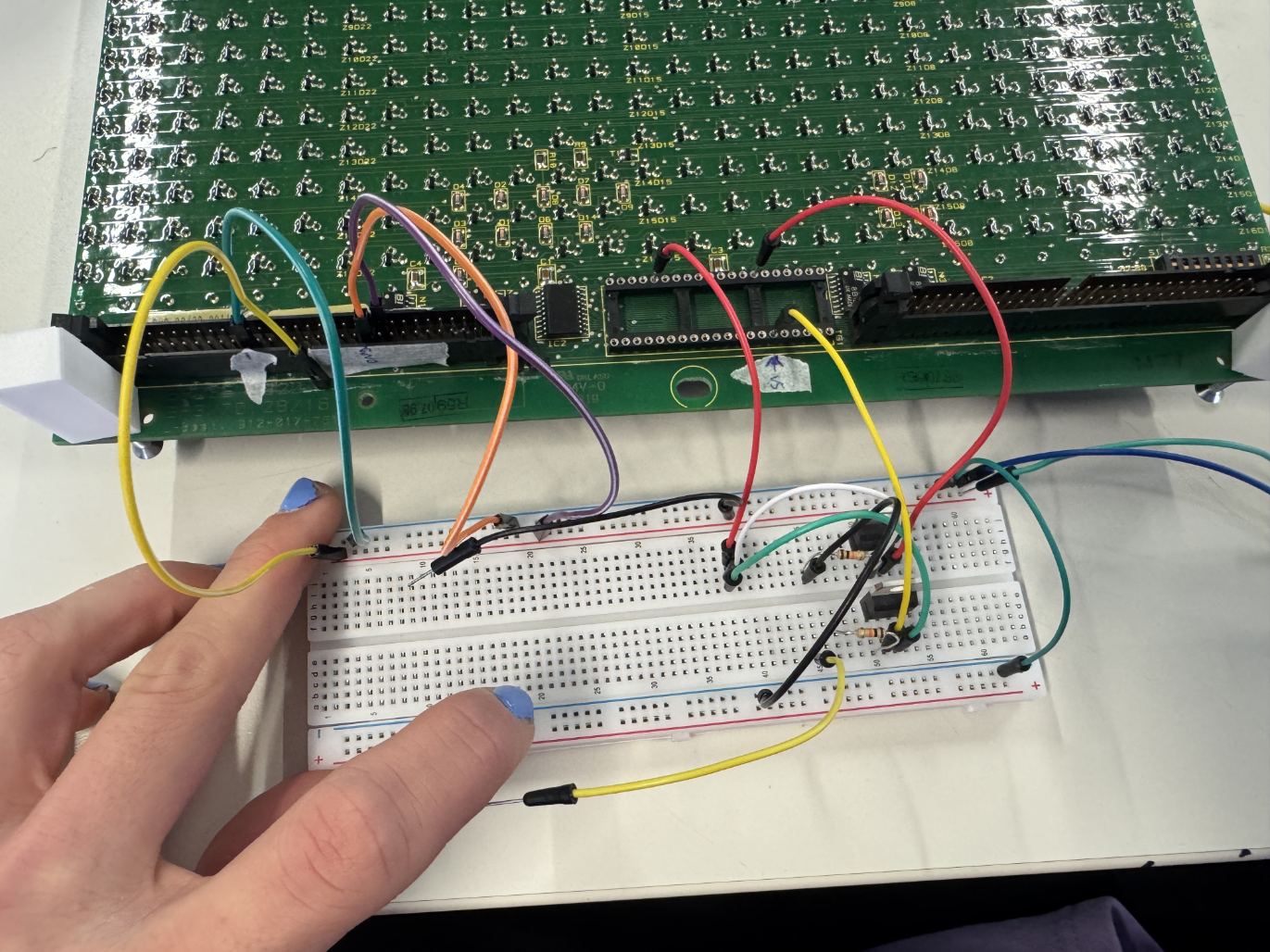
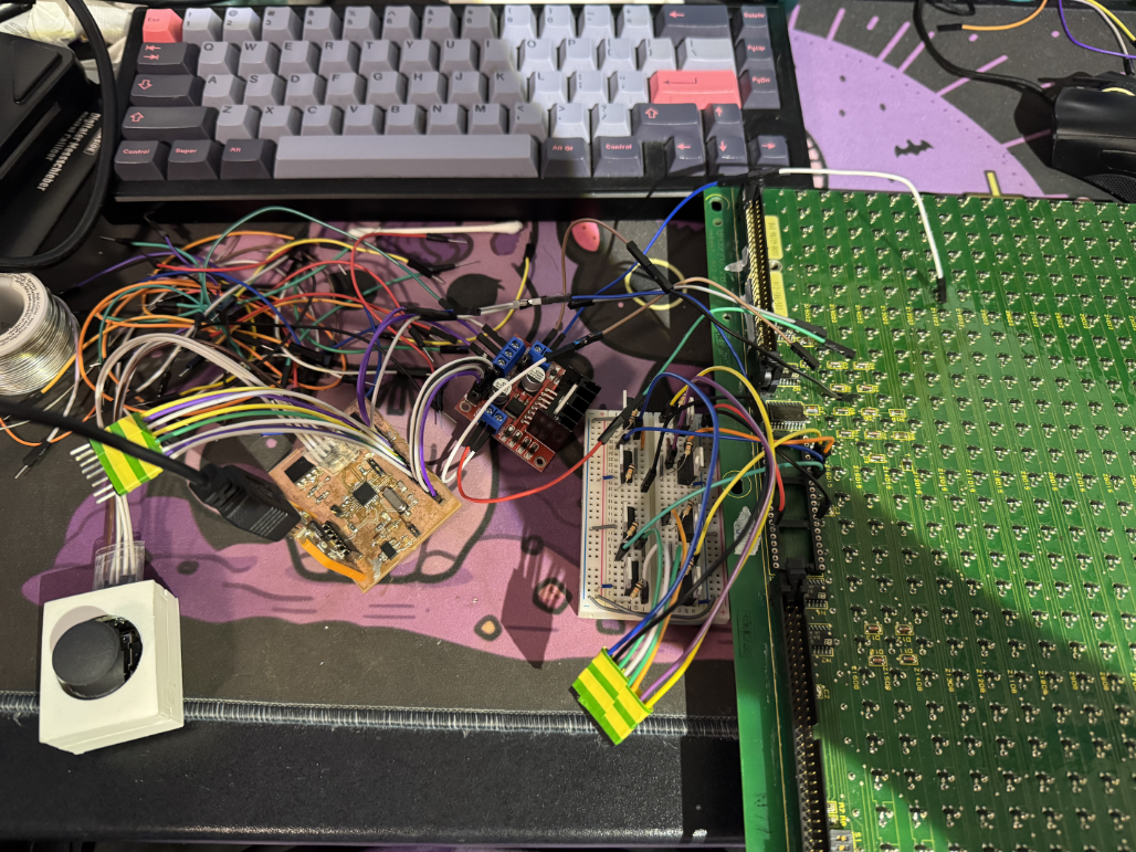 This Setup is the same principle but with 8 MOSFETs to switch the value of four rows.
BUT, since the Lab only had N Channel MOSFETs and I was running out of time, this did not work, as there was no way for me to provide a positive signal to the pin. For that I would have needed a P Channel MOSFET which was not available to me.
The Result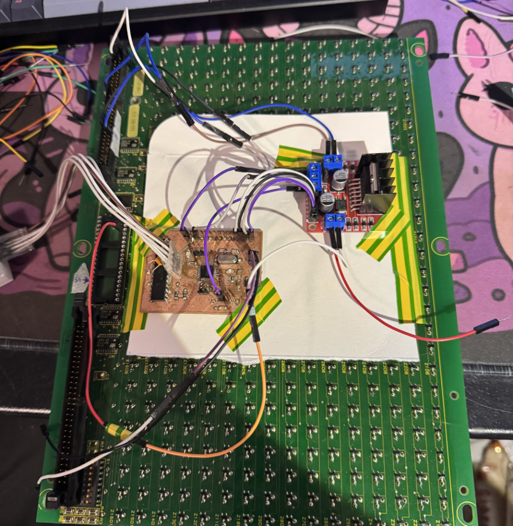
In the end I had no choice but to use the motor driver for bot the row and the column, this allowed me to switch exactly one dot. I could now flip the first dot each time the joystick was pressed.
Lessons Learned
In conclusion, while this project was very frustrating for me and I dont like that I have not managed to get at least four dots working, I have actually learned a lot.
My biggest mistake was not testing the display thoroughly enough, had I noticed the necessity for the 24V logic level at the 60pin connector earlier, I could have ordered 6 P-Channel MOSFETs and driven the chip with a Lab power supply. Since I was too afraid to test the chip and assumed I had understood it, I had no time to fix this mistake.
Another general mistake was starting too late. I should have tested the whole Flipdot module long before the end of the course so that I had time to reorder the decoder module and fix the errors I had made before.
And I learned that I should triple and quadruple check pin assignments with the actual datasheets. Although I could fix the I2C issues in software, this was entirely avoidable had I paid more attention.
Future Work
Now that I have come this far with the Flipdot module I will definitely finish developing it. I believe that I have now made nearly every mistake possible, at least regarding the Flipdot module and I would like to create a whole new board allowing me to drive the complete display.
I will play snake on this thing, and if it is the last thing I do.